Other Parts Discussed in Thread: DRV8872
Our company created our own evaluation board for the DRV8873HPWPT after frying the one made by TI: we damaged the usb communication portion of the board, so we made our own board to eliminate any external circuit from influencing our results in evaluating the motor driver.
The original circuit for our board was based on the recommendations from the data sheet with these few key details:
- Mode was connected directly to ground
- The bulk capacitance was initially selected as 220 uF; our product has a top power consumption of 96 watts (16V supply and 6 Amp stall current from motor) so we aimed for 2.3 uF per watt
- nFault was left floating (there was no micro to monitor the fault)
- Disable was tied to ground
- The slew rate was initially connected directly to ground
- the IPropI resistor values were initially set at 680 ohms; based on a max current draw of 8 amps.
- nOL and nItrip each had a toggle that would switch between DVDD and Ground
- PH, EN, and nSleep had toggles that would switch between an external 5V and ground
- The heatsink underneath the motor driver was connected the a large ground plane on the opposite side of the PCB (2 layer), with the vias placed and sized as recommended in the data sheet.
While evaluating the motor driver we followed the following procedure:
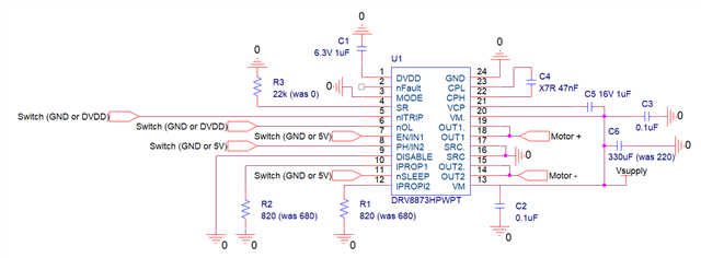
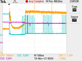
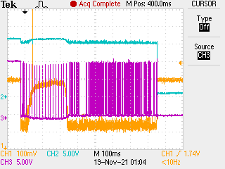
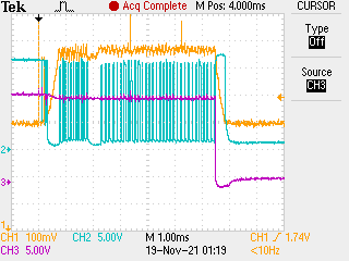
- When we connected this evaluation board to our motor we noticed that if we left the nItrip function disabled, the motor would operate at 10.5V, but would not operate at 12, 14, or 16V.
- From this point we elected to leave nItrip enabled.
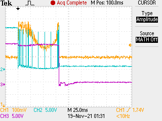
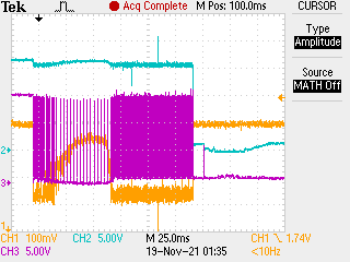
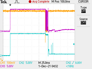
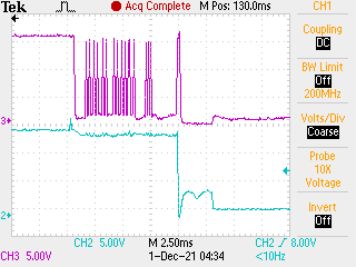
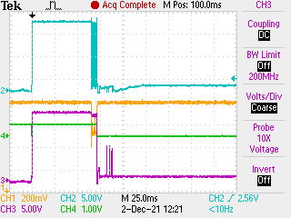
- With this enabled, it allowed the motor to operate at 10.5V and 12 V reliably, but at 14V and 16V the motor would make a clicking sound before not operating, and cycling the nSleep pin would allow it to click again (16V) or work intermittently (14V)
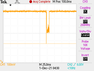
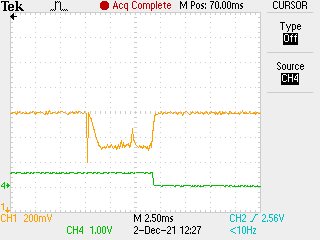
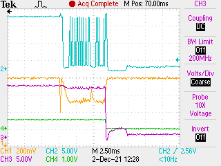
- At this point we suspected that we were somehow exceeding the OCP limit despite our oscilloscope not showing any current transients above 9 A.
- To attempt to solve this issue we tried changing the IpropI resistors to 820 ohms to limit the current to 6.7 A, but this yielded no change in behavior
- next we replaced the bulk capacitor with a 330 uF capacitor (3.4 uF per watt), but saw no change in behavior
- We also slowed the slew rate to a 22k ohm path to ground, but also saw no change in behavior.
At this point we are wondering, are we right to assume this is an OCP fault? and if that it is the case why wouldn't the IpropI resistors prevent the current from hitting 10 amps. We also considered that it could be a thermal shutdown, but the data sheet states that in that event it would attempt to operate again after a time out period.
I appreciate your help in advance,
Arturo Saenz