This thread has been locked.

If you have a related question, please click the "Ask a related question" button in the top right corner. The newly created question will be automatically linked to this question.

DRV8428: Driver is not working

Part Number: DRV8428
Other Parts Discussed in Thread: DRV8884, DRV8885, DRV8886,

Dear Sir,

We have used stepper motor driver IC DRV8884 since long time. It works perfect in production.

We are using stepper motor at 12V / 300mA per winding.

But, unfortunately due to unavailability of stock of DRV8884,DRV8885,DRV8886, we have to change the IC & have to find alternative of DRV8884.

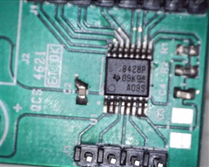
We have found DRV8428, which can be fitted with our criteria.

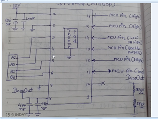
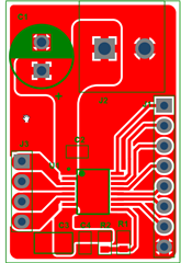
We have designed one prototype of DRV8428. Design specification is as below:

1) Enable & Sleep pin always logic high by MCU(3.3V). currently we have disabled sleep mode & Enable MOSFETs.

2) input step frequency at STEP pin 800Hz(square wave pulse train).  DIR pin is logic high OR low by MCU. (3.3V / 0V, both has been tested)

3)VM = 12V with all necessary capacitor (200uF // 10nF)

4)PGND / GND / Thermal Pad - all are grounded.

5) DVDD = we get 5V output from IC which is perfect as per design.

6) VREF = by using resistor devider network(8200 ohm & 1800 ohm) & DVDD of IC, we have set 0.9V which is also perfect as per design.(for 300mA, Vref should be 0.9V as per equation given in datasheet)

7) Microstepping Pin = M1 logic high (3.3V) & M0 logic low (1/4 Microstepping)

8) Decay = 0 = Smart Tune

Now Queries are as below:

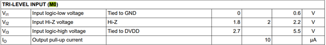
1)  Microstepping Pin M0 : It is TRI-LEVEL input pin.

This pin is internally pulled down in the IC. We are able to make it logic high OR logic low by MCU.

but how to make it High - Z mode?

If we left it open or floating, it is measured as logic low because of internal pull down resistor. If we measure voltage then we get 0V.

2) Main issue is We do not get pulses on A1, A2, B2. these 3 pins remains at 12V.

only B1 gets the pulses.

I have checked this with & without connecting Stepper motor. but both time result is same. only B1 gets pulses & all others remains at 12V.

I have tested this with DRV8884 with & without connecting Stepper motor., All terminals (A1,A2,B1,B2) gets pulses perfectly both times.

So, I am confused now, what could be the problem so that only one terminal gets pulses, all other remains at 12V. this is strange. isn't it?

Please help me to sort out my queries.

Regards,

Jigar

  • Hello, Jigar,

    1. M0 pin has 200kohm pulldown resistor and also has 10us pullup source. The connection can be found in the device function block diagram in the datasheet.

    If you left it open or floating, it should be around 2V.


    2. DRV8428 has a current regulation according to the VREF setting. A1 and A2 cannot both be 12V which cannot provide any current the output. Would you share your schematic and layout? 

    Regards,

    Wang Li

  • Hi Wang,

    Thank you for your Guidance.

    "

    1. M0 pin has 200kohm pulldown resistor and also has 10us pullup source. The connection can be found in the device function block diagram in the datasheet. If you left it open or floating, it should be around 2V.

    "

    Yes, I completely agree with you. But when I have measured with Multi Meter & DSO, It shows 0V. Is this means current source is not working in the IC? pulled down is working, so I got measured value 0V.

    2. please find below the schematic.

    I got Dvdd_Out 5V from IC, which is OK. I have used this voltage for Vref which is set to arouund 900mV. This is also perfect.

    IC outputs pulses on B1 terminal only. all other A1, A2, B2 remains at 12V steady for all time while I am applying pulse train at pin 13 (STEP pin).

    I think, If M0 pin issue is solved , there might be a chance that whole circuit will work OK.

    But why current source is not working at M0 pin?

    I have checked if this pin shows short circuit with ground? But no, it does not shows short circuit with ground.

    So, can you help me to solve this issue first? Then  we will check pulses issue.

    Regards,

    jigar

  • Hello, Jigar,

    Let me take a look now.

    Regards,
    Wang Li

  • Hello, Jigar,

    I didn't find the issue from the schematic. I would think the device get damage or the device soldering issue which causes A1, A2, B2 at 12V all time.

    How many boards do you build? Do they all have the same issue?

    Regards,

    Wang Li

  • Hi Wang,

    I have checked 2 ICs on same board. But both time they didn't work.

    You may right that there may be a chance that IC got damaged while soldering OR Part comes Faulty.

    Let me see that & will inform you.

    Thanks,

    Jigar

  • Jigar,

    Can you share the device top marking? Also, using an EVM as reference to compare with your board may speed up the debugging process.

    Regards,
    Wang Li

  • Hi Wang,

    Sorry for late replay.

    Please find below pic of the top marking of IC DRV8428.

    Please find below pic of the layout.

    C1=220uF, C2=10nF, C4=1uF(previously it was 470nF), R2=8K2, R1=1K8.

    Still problem is not solved yet.

    I have changed IC for 3rd time.

    Still M0 shows (which is open circuited currently) shows 0V instead of 2V.

  • Hello, Jigar,

    From the top marketing, the device is not DRV8428 (Step/dir interface device). It is DRV8428P (PWM interface device). They are different device.

    Would you get DRV8428 device to run your board?

    Regards,

    Wang Li

  • Hi Wang,

    Thank you very much to solve this issue.

    I can't believe that this can be happened. Two ICs with almost same part no can exist. the only difference is extra 'P'.

    Our purchase dept. has no idea of this.

    Once again, thank you very much for the guidance.

    We will purchase 'DRV8428PWPR' instead of 'DRV8428PPWPR' & move forward.

    Regards,

    Jigar