This thread has been locked.

If you have a related question, please click the "Ask a related question" button in the top right corner. The newly created question will be automatically linked to this question.

DRV8818: the maximum continuous output current

Part Number: DRV8818
Other Parts Discussed in Thread: DRV8434S, DRV8434A

Hi team,

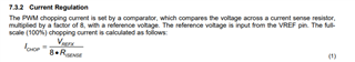
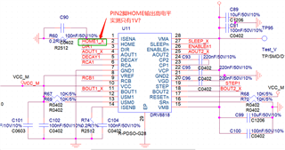
The customer intends to use use the DRV8818 to drive the stepper motor, and now would like to know the maximum continuous output current of the device, and is this continuous current achieved by adjusting the ISENA/ISENB pin-to-ground resistance?

Could you help check this case? Thanks.

Best Regards,

Cherry

  • Hi Cherry,

    I will be happy to help you out today. The maximum continuous output current is going to be determined by two factors, first the current regulation chopping threshold and second the maximum current that the device can sustain before thermal limitations become an issue.

    For the current chopping threshold:

    You are right that it can be adjusted via the ISENA/IISENB pin to ground resistance, as well as by changing the reference voltage. You can set the current chopping threshold as follows:

    However this will only control what is the maximum current that the device allows via current regulation. The bigger consideration for continuous current will be heat dissipation. If continuously driving the device causes the temperature to rise above 150C then the device will enter into OTS (Over Temperature Shutdown). In order to figure out what continuous current you can run before this happens you will need to run thermal calculations on the particular layout being used.


    Section 10.3 of the datasheet goes into more detail regarding these calculations.


    Best,

    Pedro Arango Ramirez

  • Hi Dear Pedro,

    Thanks for your support and here comes some additional questions:

    1. What's the purpose of driving the IC DRV8818 HOME pin? Can the drive IC DRV8818 signal the master detection after the motor is blocked?

    2. The stepper motor drive is powered by the DRV8818 using VCC 3.3V, and currently when debugging the circuit, the PIN2 pin (HOME pin) actually outputs only 1V high, The PIN2 pin is normally at a minimum high level of 0.7 VCC ,what is the reason for that?

    Could you also help check this? Thanks.

    Best Regards,

    Cherry

  • Hi Cherry,

    Regarding the home pin, you do not need to drive, it is instead an output that can be read. It notifies the user when the device is at the home step of the logic table. This should be at 45 degrees of step angle. Attached is a table that explains it's function: 

    Regarding if the DRV8818 can signal the master detection after the motor is blocked; it unfortunately does not have stall detection capabilities. Devices that feature it at the moment are the DRV8889Q1, DRV8434A, and the DRV8434S. However if you really wanted to know if the motor is stopped you could attach a current monitor to one of the windings, if the current shoots up for a transient while the motor is static then it could signify that the device is stalled and current regulation kicked in. 

    Regarding your second question about the Home pin, at 3.3V the low output should be around 1V (0.3*Vcc) and this should only happen when the indexing table is in the home position, the high output should be around 2.3 V (0.7 * Vcc) and this should happen at any other position rather than home. Is this not happening at the moment?

    Best,

    Pedro Arango Ramirez