This thread has been locked.

If you have a related question, please click the "Ask a related question" button in the top right corner. The newly created question will be automatically linked to this question.

DRV2700: Driving piezoelectric actuator

Part Number: DRV2700

Hello,

I am planning to use DRV2700 in my project to drive a piezoelectric actuator.

The actuator needs DC voltage from 0 to 150 VDC, the output voltage shall be variable from 0 to 150VDC insteps of 1 VDC.

The actuator has a capacitance of 26uF. Can the flyback configuration using DRV270 be used for the above application.

Regards,

Arun R

  • Hi Arun,

    The DRV2700 with a flyback configuration will be able to drive 150VDC with 1V steps.

    You can look at the DRV2700EVM-HV500 users guide which contains a schematic you can base your design on. you will need to select different value to achieve 150V. The  DRV2700EVM-HV500 users guide has an example of a configuration for 158V


    However 27uF is a relatively large capacitance for an actuator. this will greatly reduce the frequency you will be able to drive without attenuating your output signal, but for low frequency and DC this should be OK.

    Regards,
    Arthur

  • Hi Arthur,

    Thank you for immediate response. We are using the piezoelectric actuator to either open or close  a valve. So it is a low frequency application.

    Other than the datasheet and the  DRV2700EVM-HV500 is their any detailed design guide and simulation models on DRV2700 from TI.

    Regards,

    Arun R

  • Hi Arun,

    Those two documents I mentioned will have some equations you can use for selecting the value of the components for the flyback circuit. but I dont have any other detailed design guides.

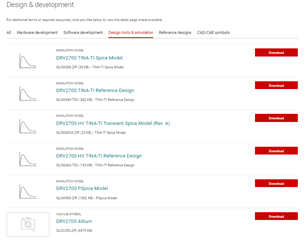
    However there are several spice models and reference designs available on the device product page that you can use to simulate the design https://www.ti.com/product/DRV2700#design-tools-simulation 

    Regards,

    Arthur

  • Hi Arthur,

    Thank you for the quick response. I had one more query on the duty cycle of PWM signal.

    Since I am trying to generate DC voltage from 0 to 150 VDC, and want to increase the output voltage in steps of 1VDC or 1.5VDC. 

    I would like to know is there any formula which relates the PWM duty cycle and the output voltage. This will help me programming the duty cycle of PWM to get the exact output voltage needed.

    Regards,

    Arun R

  • Hi Arun

    If you have not already I would recommend you read the DRV2700EVM-HV500 Users guide because it will explain how to calculate the HV output in some detail (specifically sections 4.1) slou407a

    From your perspective. Since you want to change the DC voltage of the output you will want a high PWM frequency >20 kHz. PWM at this frequency will be mostly filtered out and appear much closer to a DC control signal.

    Regarding the exact duty%:HV output relation is difficult because it will depend on the PWM drive strength and the value chosen in your flyback circuit.

    I tested this on an DRV2700EVM-HV500 and set it up with 158 V max output, 20 kHz PWM frequency and then stepped through in 1% resolution (piezo control console software only increments PWM in 1% increments) and my piezo actuator was in the 10's of nF capacitance. 

    1% - 360 mV

    2% - 597 mV

    3% - 605 mV

    4% - 2.96 V

    5% - 4.19 V

    6% - 5.69 V

    50% - 78.70 V

    51% - 80.62 V

    52% - 83.06 V

    53% - 85.49 V

    95% - 151.01 V

    96% - 152.82 V

    97% - 154.85 V

    98% - 156.1 V

    99% - 156.8 V

    note: the % represents the "low" portion of the signal. i.e. 1% means 99% 'high' 1%'low'

    As you can see the relation of output voltage and PWM duty% is not exactly linear.

    But if you are able to realize a PWM driver that can achieve >20kHz frequency, and you can control the duty cycle in 0.5%-0.1% then it is reasonable that you can accurately control the voltage in 1VDC increments.

    I hope this helps. 

    Arthur

  • Hi Arthur,

    Thank you for the detailed response. I was trying to simulate the flyback circuit using the SLOM404.TSC TINA reference design. I tried to change the circuit for output DC voltage by changing the VPWM signal to a PWM signal and by varying its duty cycle. But I see the amplitude of the PWM signal also has an impact on the output DC other than the duty cycle. In our response you have explained how you were varying the just the duty cycle to get the varying DC output. But were you also varying the amplitude of PWM signal to the filter?

    Regards,

    Arun R

  • Hi Arun, 

    You are correct that the amplitude of the PWM will affect the voltage.

    On my EVM I was not varying the PWM amplitude. the PWM is coming out of MSP430. the amplitude was 3.41 V

    Regards,

    Arthur

  • Hi Arthur,

    Thanks for the response.

    Is there any equation which relates the input PWM amplitude with the amplitude of the DC output.

    Regards,

    Arun R

  • Hi Arun, 

    this formula for calculating the high voltage output can be found in the data sheet

    this formula is implying that when the PWM output is equivalent to 1.3 V (when PWM output is equal to Vfb) then the high voltage output is 0V.

    and when the PWM output is 0V the high voltage will be its maximum

    Regards,

    Arthur

  • Hi Arthur,

    Thank you for the response. I am using the file slom404.tsc for my flyback simulation.

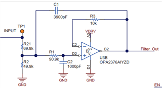
    I tried changing the duty cycle of a 25kHz PWM signal with an amplitude of 1.3V. But the output is not varying as expected as per duty cycle. For 90% duty cycle ideally I should get very low output around 10V to 15V but I am getting around 50V. Also this output amplitude varies with the load capacitance. Can you please let me know why the simulation behaves as above. Also I observed that the integrator and LPF circuit shown in the figure 37 of datasheet  and circuit shown in page 20 of user guide is different. In datasheet it is a inverting integrator and in user guide it is non inverting integrator. What could be the reason for this?

    Thanks and Regards,

    Arun R

  • Hi Arun,

    are you filtering your PWM before applying it to the flyback circuit? if you are using a 1.3V pwm amplitude and passing it through the below circuit you might be attenuating the PWM more than intended.

    If I where you I would verify the flyback circuit is working (perhaps use a DC source in your simulation) before trying to integrate the PWM.

    Regards,
    Arthur

  • Hello,

    Thank you for the response. I tried to check the working of flyback circuit using a DC source instead of PWM generator.

    But the circuit is not behaving as desired. When I give 0V at the bottom of the resistor divider network, theoretically i should get the maximum DC output. But I am getting 0V as output. What could be the reason for this?

    Regards,

    Arun R

  • Hi Arun,

    Can you please share the simulation schematic and I will look at it?

    Regards,
    Arthur

  • Hi,

    How can I share my simulation schematic to you. I do not see the option to upload the schematic.

    Regards,

    Arun R

  • Hi Arun,

    You can drag and drop files into the comment text box to attach, or you can copy+paste a screen snapshot

    Regards,

    Arthur

  • Flyback.TSC

    Hello,

    Please find the schematics I used for simulation. The basic schematics was taken from slom404.tsc from TI.

    Regards,

    Arun R

  • Hi Arthur,

    Any updates on the simulation file I sent. Is there any feedback from your side.

    Regards,

    Arun R

  • Hi Arun, 

    I have not looked at the simulation yet. things have been quite busy here. I will look at it tomorrow and see if i am able to get it to work.

    Regards,

    Arthur

  • Hi Arun,

    I took a look a the simulation and it does seem to not work at all. with the unmodified reference design, as you likely know, it does work. 

    The only way I was able to get it to work at a constant 500V HVDD was to remove the VPWM voltage source and connect that node to ground.

    This is incorrect behavior from the simulation as the real device does not function like this. I just tested on EVM and the voltage should be at its maximum value when that node is grounded.

    perhaps you can simulate this circuit to find the correct values to achieve 150V and then proceed with a board design and tune the PWM circuit the old fashioned way (on the bench)

    Regards,

    Arthur