This thread has been locked.

If you have a related question, please click the "Ask a related question" button in the top right corner. The newly created question will be automatically linked to this question.

DRV8353R: DRV8353RS Current limit of VCP and VGLS pin

Part Number: DRV8353R
Other Parts Discussed in Thread: LM5008A, DRV8353

Hi Motordriver Team, 

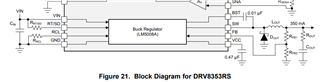
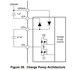
What would be the current limit of the VCP and VGLS pin of the DRV8353RS? The datasheets states that the VGLS pin is the output of the voltage regulator.  LM5008A, which is used as an integrated buck, can provide a maximum of 0.35 A . Does this mean the current limit of VGLS is 350mA? I could not find any information on the current limit of the VCP pin.

A fast response would be highly appreciated. 

Thank you for your support.

Best,

Angelika 

  • My bad VGLS is connected to the output of the linear regulator. Page 34 states that both pins ( VGLS and VCP) can provide 25mA (on average). What would be the maximum possible current limit for these pins? 

    Thanks and best regards, 

    Angelika 

  • Hi Angelika,

    Thanks for the follow-up message and clarification.

    1. you are correct in saying that VGLS is the linear regulator pin of the DRV8353RS device, and not the buck output (which is separate)  
      1. like the section you mentioned in the datasheet, this VGLS functionality in the device is meant to supply up to 25mA for device internal operations, like providing gate-drive voltage and gate-drive current for the LS drivers 
    2. VCP is the charge pump circuitry internal to the DRV8353RS device -> this is primarily meant to provide gate-drive voltage for the HS drivers 

    I don't think there is an explicit spec for the VGLS regulator output current capability, because that pin is not meant to drive other voltages external to this device. We do not recommend connecting any external circuits on the PCB to source voltage/current from the VGLS pin, or it may interfere with the DRV8353 device's low-side gate driver operation. 

    For VCP, the same situation applies and it also has an average output current capability of 25mA (page34 also) - this charge pump regulator functionality is only meant to support the DRV8353's internal operations, and should not be loaded with additional external circuitry expecting a power supply source. 

    If there is a regulated power supply need on the PCB system, the integrated buck regulator is meant to solve that need

    • current capability being up to 350mA, 2.5V-75V output voltage 

    Thanks and Best Regards,
    Andrew

  • Hi Andrew,

    thanks for the reply.  I would have another question. Do the pins have an internal current limit? On both pin a ceramic capacitor (eg. X7R 1uF) should be used. Assuming this capacitor breaks and produces a short. What would be the max current from the VCP or VGLS? Because if the current is not somehow limited and eg. 100mA are  rushing over the 0603 / 0805 parts the PCB might start burning. Is there internal currentlimit for these outputs which would avoid this? 

    Thanks and best regards, 

    Angelika 

  • Hi Angelika, 

    Thanks for the follow up response -

    In the case of external component damage, such as a faulty VCP-Vdrain capacitor or CPH-CPL capacitor,

    • I think it may be best to refer to the datasheet's 'Charge Pump Architecture' section on page34 
    • There is a circuit internal to the device that manages the charge pump regulator, and there are certain features like Charge Pump undervoltage that will detect when the charge pump is not generating the expected voltage that is critical for device operation, and raise a flag signal on the nFAULT pin to report the error. The fault condition taking place would also shut down parts of the device to prevent further operation that could cause damage
    • I think the charge pump controller logic in this case would help manage the problem scenario you mentioned 

    Best Regards,
    Andrew

  • Hi Angelika, 

    Closing this thread for now - please help mark this thread as resolved if the answers helped solve your problem. 

    And do feel free to reach out again if there are any further questions or comments for motor driver devices. Thanks! 

    Best Regards, 
    Andrew