This thread has been locked.

If you have a related question, please click the "Ask a related question" button in the top right corner. The newly created question will be automatically linked to this question.

DRV8703-Q1: Gate Drive Failure when Stopping a PMDC operating in PH/EN Mode

Part Number: DRV8703-Q1

Hello

We are using the DRV8703-Q1, to drive a 30V/350W PMDC motor, with suitably sized MOSFETs (1.9mOhms / 60V). When we stop the motor (via Signals PH/EN), we are seeing physical failure (package burnout / damage) of the DRV8703-Q1. This happens at 100% PWM as well as lower PWMs. We are not decelerating the motor in this case, its an abrupt stop (emergency stop). 

There is no load on the motor, just a gearbox. 

We are seeing two types of failures

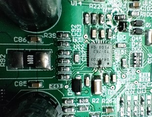
1. The physical failure is near the Vm pin (physical proximity - this may not be the Vm pin itself). 

2. The physical failure is on the Vm pin(image below). 

This is a HVM product and we need to get to the cause of these failures and fix them thoroughly asap to go into production. I can share more details as needed to troubleshoot these. 

  • Hello Deepakji,

    I am happy to assist you today. The failure that you are describing seems to me due to supply pumping issues during emergency stop, essentially exceeding the maximum voltage that the part can handle. This is a system's level problem, therefore I would suggest looking into the following link "The art of stopping a motor" that can suggest different ways in which you can avoid supply pumping:

    https://e2e.ti.com/blogs_/b/industrial_strength/posts/art-of-stopping-the-motor-vm-pumping

    Hopefully the link proves insightful. Let me know if I can help with anything else. 

    Best,

    Pedro Arango Ramirez. 

  • Pedro Arango Ramirez.

    Thanks for the recommendation and the link, I did go through this and after thinking this over and doing some quick testing I have concluded on the following.

    1. Switch my control mode to Standard PWM mode - This allows me coasting to stop and hence resolves my Vm pumping issue. However, this reduces my efficiency and control at lower PWMs.

    2. So I am now making both PWM signals low (coasting) when I want the motor stopped. 

    3. To run the motor I am initially making both PWM signals high (brake slow-decay). 

    4. Then to run motor forward keeping one of the PWM high I am driving the other PWM signal low to the required duty cycle. 

    5. To run the motor reverse I am keeping the alternate PWM signal high and driving the other PWM signal low to the required duty cycle. 

    This procedure allows me the efficiency and control of PH/EN type control and also the Coasting stop to prevent Vm pumping. 

    Is this acceptable / normal practice. Are there any known / potential issues with this type control? 

    Are there any PWM signal safe guards that I should be considering when using this type of control. 

    If any of this needs more clarity or explanation, please let me know. 

    Thanks!

  • Hi Deepakji,

    I'm going to take over this thread from Pedro.

    Firstable, I think you are mistaking coasting for brake (slow decay). Below is a diagram of the H-bridge. The VM pumping occurs when the current flows back to the VM supply which happens when coasting (all FETs High-z). To prevent VM pumping, the decay mode needs to be set to slow decay (brake).

    2. So I am now making both PWM signals low (coasting) when I want the motor stopped

    The PWM signals need to be both HIGH to stop the motor. (sets it to brake mode)

    3. To run the motor I am initially making both PWM signals high (brake slow-decay).

    Can set both signals LOW to disable all FETs when not driving the motor.

    when going from driving to braking, the PWM duty cycle will be flipped. Meaning, to increase the motor speed, the duty cycle of the corresponding output will need to be lowered.

    Other than that, I think this procedure works. We offer the two decay modes, braking and coasting, to allow for more design flexibility.

  • Pablo

    Thanks for clarifying on the following. 

    when going from driving to braking, the PWM duty cycle will be flipped. Meaning, to increase the motor speed, the duty cycle of the corresponding output will need to be lowered.

    Other than that, I think this procedure works. We offer the two decay modes, braking and coasting, to allow for more design flexibility.

    However, getting back to the Vm pumping and coasting / braking modes. I am referring back to the following TI article, which is clearly suggesting that coasting causes no Vm pumping, with scope captures to show Vm pumping in slow decay mode when PWM is reduced from 100% to 50%. 

    https://e2e.ti.com/blogs_/b/industrial_strength/posts/art-of-stopping-the-motor-vm-pumping

    quoting from the article

    "Because in coast method all FETs are off during PWM off time. No reverse current can be built up and also the BEMF < VM will prevent the current flow into supply."

    I also see the diagram you have shared and that is showing a current path through body diodes when the MOSFETS are Hi-Z. 

    Please help understand.  

  • Hi Deepakji,

    Sorry, there was some confusion from my side. Let me clarify and explain VM pumping in simpler terms. The article may have been a bit confusing to understand.

    VM pumping is caused when there is a build up of reverse current (opposite to the original current direction before deacceleration) during the slow decay phase (PWM off time). During slow decay, the current in the motor will begin to rapidly decay and after some PWM cycles, the BEMF will overtake the VM and reverse the motor current direction (as shown in block C on the image below). At this point, the motor is effectively behaving as a generator and will pump current into the supply during the PWM ON time (due to the inductive nature of the motor).

    The reason why VM pumping does not occur during coasting (all FETs disabled) is because the current direction is not being reversed during deacceleration so the motor never behaves as a generator. Likewise, when deacceleration directly to 0% duty cycle, even in coast mode, there is no time for the current to reverse and VM pumping will not occur.

    The best way to minimize the VM pumping is to gradually decrease the PWM duty cycle over a longer period of time (when in coast mode). This will prevent the current from rapidly decreasing.

    Another option is to operate in coast mode which has the tradeoff of lower effeciency and motor control specially at lower duty cycles.

    The procedure you described in your earlier post is acceptable. During normal operation, you can alternate between driving and braking. During de-acceleration,you can switch from driving to coasting.

  • Pablo

    I cannot say I am clear on this yet. However, we did some experimentation and I think we have resolved this for the time being, by decelerating over a long period in our case. 

    I have another question regarding current measurements on the DRV8703Q - should I create a sperate thread for the same? 

    Question is the datasheet mentions "VIO is typically 5 mV (input referred)." but we are seeing considerable variations on this from one IC to another (all from same production batch / reel). Our observation shows that this varying from 2mV-5mV. Is this possible? The datasheet does not offer any range to this offset. Also please help understand "input referred".  

  • Deepakji,

    Thanks for the update.

    I have another question regarding current measurements on the DRV8703Q - should I create a sperate thread for the same?

    Yes please.