This thread has been locked.

If you have a related question, please click the "Ask a related question" button in the top right corner. The newly created question will be automatically linked to this question.

DRV8704: Pre-Driver Fault (PDF) on High Power motor

Part Number: DRV8704
Other Parts Discussed in Thread: DRV8711, , CSD18540Q5B

Hi All,

Recently, i have a new designed dual channel dc controller board from a engineer.

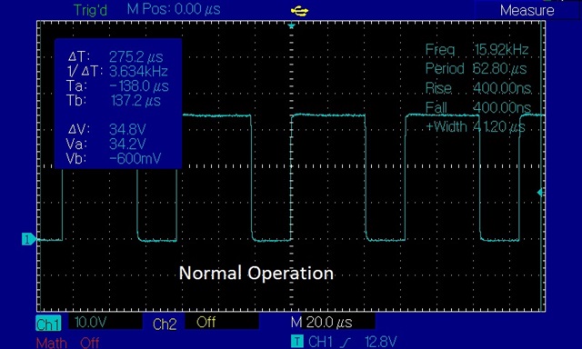
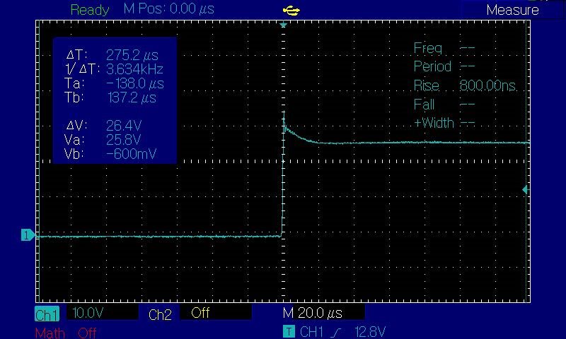
It's been tested ok from the engineer using smaller motor. However, when we test the board using high power motor, it occasionally flagged Pre-driver faults(say 2 out of 10 times).

Here are the details of board and equipments used:
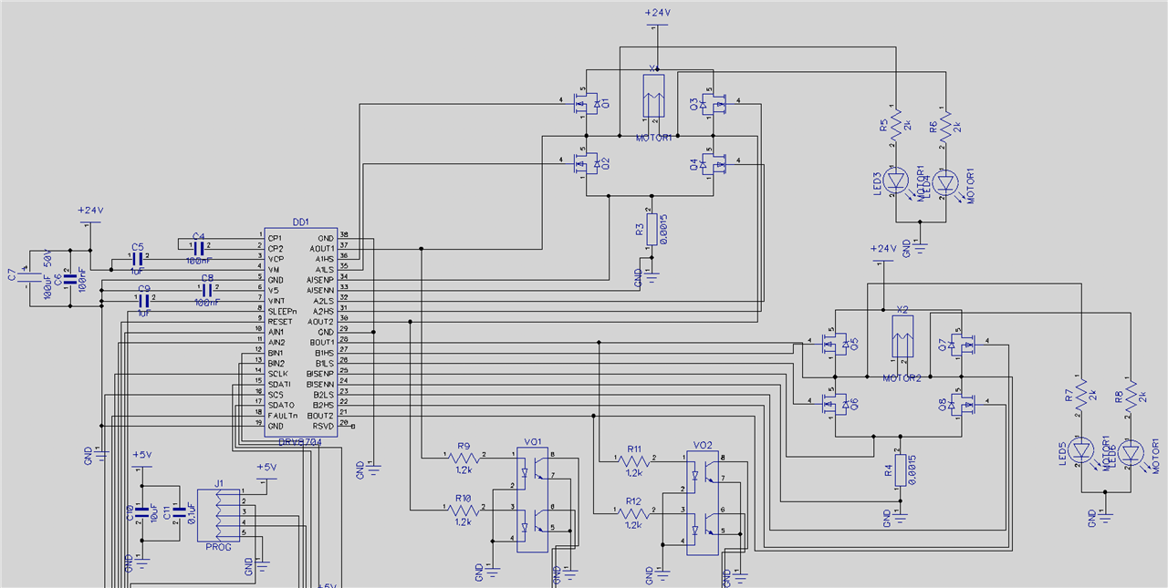
Driver: DRV8704

Mosfet: IRFH7440TRPBF

Shunt Resistor: 0.0015 Ohm 3W

Motor 1: 24V 800W(34A max)(pre-driver faults occasionally)

Motor 2: 24V 240W(10A max)(no pre-driver faults)

Following settings used(other than default values):

DTIME: 880 ns

TOFF: 48us

TBLANK: 1us

TDECAY: 8us

DECAYMOD: AUTO MIX

TDRIVEN/TDRIVEP: 2.1 us
 
Schematic as follow

Thanks in advance

Richard 

  • Hi Richard,

    Can you provide a waveform of the gate voltage of the FET experiencing the PDF fault. Also include the nFAULT pin and output voltage of the corresponding FET.

    Can you set IDRIVEN and IDRIVEP to the highest values (400mA/200mA). Does this fix the PDF faults?

  • Hi Pablo

    Thanks for your reply.

    IDRIVEN and IDRIVEP are already set to max values(400/200mA).

    I don't have waveform handy(not the oscilloscope expert). i will try to capture it with PDF fault.

    The other thing is(not sure if it's related), when we left DTIME to the default value(410ns), it's actively chopping the current to about 10A.

    after reading this thread https://e2e.ti.com/support/motor-drivers-group/motor-drivers/f/motor-drivers-forum/749003/drv8711-predriver-fault-xpdf-detection

    i increase the DTIME to 880ns without adding resistor, the current chopping issue is gone.


    Base on my rough calculation of gate charging current, it requires about 300mA with given drive time 2.1us.

    Do you know if the DRV8704 regulate the charging current or does it flag the fault if it provide more than 200mA to the gate?

  • Hi Richard,

    I don't have waveform handy(not the oscilloscope expert). i will try to capture it with PDF fault.

    If you get the opportunity, please send me the oscilloscope waveforms.

    The other thing is(not sure if it's related), when we left DTIME to the default value(410ns), it's actively chopping the current to about 10A

    Can you clarify what you mean? Are you saying the current regulation is changing based on the DTIME? DTIME should not be affecting current regulation.

    I looked through this post. Increasing the DTIME will help prevent any coupling or noise that happens when a FET is disabled/enabled from causing a PDF fault. The gate resistor is recommended to slow down the slew rate at the switching node which can reduce any noise caused by parasitic capacitance and inductance on the high di/dt traces.

    Base on my rough calculation of gate charging current, it requires about 300mA with given drive time 2.1us.

    Can you explain how you calculated this value? Did you take into account the gate charge of your MOSFET?

    Do you know if the DRV8704 regulate the charging current or does it flag the fault if it provide more than 200mA to the gate?

    The DRV8704 essentially sources a continuous amount of current to the gate of the MOSFET so it's not regulating it.

  • Hi Pablo

    Thanks for the reply.

    I have manage to capture some waveforms on the gate pin of mosfet. Sometime the wave is perfect (photos with normal written on it).

    I noticed, when the wave goes abnormal, the frequency goes up(unstable) and motor is stalling and making inconsistence high pitch noise.

  • Hi Richard,

    Thanks for providing the waveforms. There abnormal gate voltage is definitely causing the PDF fault. The abnormal waveforms seem to be the result of current regulation. In a previous post, you mention that increasing the DEAD time to 880ns helps with the current regulation issue. What exactly is this current regulation issue? Does the PDF fault go away when increasing the dead time?

  • Hi Pablo

    with Dead time and Isgain at default values. The current can only goes up to 15A, as soon as it draws over 15A, it was chopped to 10A.

    Then I changed the isgain from 40 to 20v/v. It went straight to PDF fault every time.

    and then I also increase the dtime to 880ns, it is able to handle 25A, with occasionally pdf fault and abnormal waveforms as pictures above.

  • Here is the video, first half of the video is working fine(forward). The second half, the waveforms went crazy, I was doing reverse on the motor. This is electric hydraulic actuator, it requires more power on retraction.

    however, when I change the motor to 200w, it works fine for both forward and backward.

    drive.google.com/.../view

  • Richard,

    Since this issue seems to be far worse at high power, I think trying a series resistor and highest dead time is something you should try.  

    Please see section 8.1.2 in the datasheet.

    8.1.2 Optional Series Gate Resistor

    In high current or high voltage applications, the low side predriver fault may assert due to noise in the system. In this application, TI recommends placing a 47 to 120-Ω resistor in series with the low side output and the gate of the low side FET. TI also recommends setting the dead time to 850 ns when adding a series resistor.

    Are you able to cut the traces and try inserting some resistance?  

    Regards,

    Ryan

  • Hi Ryan

    Thanks for the reply.

    i'm not able to find the section 8.1.2 in the datasheet of DRV8704.I will try to add resistors you mentioned tomorrow. Can you please clarify the locations of the resistor required? are the resistors only required on low side gate? and where is the low side output(of the DRV8704?). I have seen others design of putting resistors on both high and low gates. is that prefered?

    Thanks

  • Richard,

    My apologies...that section is in the DRV8711 data sheet which is a similar device.  

    Please try putting the resistors only on the low side gate.  They would be placed in series between the low-side FET gate signals from DRV and the actual gate of the low-side FETs.  

    Regards,

    Ryan

  • Hi Ryan

    I have managed to cut the traces and place 47ohm resistor between drv8704 and low side gates. it doesn't help much.

    However, i tried to change isgain down to 5v/v. The waveforms become normal regardless the load. And the frequency become stable.

    But the Pre-driver faults still occurred. it happened at beginning of the action when i change the motor direction. even-though i placed 2 seconds delay between change of directions.

    Here is the waveform i catch when the PDF fault happened, it only does on and off then PDF fault.

  • Hi Richard,

    Could you try the following?

    - to place small MLCCs around 220pF-1nF between AISENN and AISENP (BISENN and BISENP) close to DRV8704 pins,

    - to place some LC filter between driver and motor to filter any noise coming from motor brushes, some big ferrite cores might be good as well,

    - increase TBLANK to 2-3 us,

    - place one MLCC 1uF-2.2uF for each H-bridge between +24V and GND (or LS Mosfets Sources).

    Are AISENN and AISENP  (BISENN and BISENP) traces routed as differential pairs?

    Regards,

    Grzegorz

  • Richard,

    Grzegorz's suggestions are good. See if you can get any good results. This might be the an edge case where the extra noise caused at high power is triggering the PDF fault. Minimizing any noise from the motor or switching can help.

  • Hi Richard,

    Any updates?

  • Hi Pablo

    Sorry for the late reply. I have passed the Grzegorz's suggestions to my engineer.

    However, i did tried to increase TBLANK to 2-3 us, which results pre-driver fault every time.

    I have also ordered a 8704EVM to see if the problem is our board design.

    I will post some updates once I tested 8704EVM.

    Thanks

    Richard

  • Richard,

    Thanks for the update. Let me know once you get some data results.

  • Hi Richard,

    Last time I mentioned some techniques for switching noise filtration but problems caused by noise may not be the case, though I think it is worth of trying.

    Pablo said about current regulation causing abnormal waveforms. I have not used DRV8711 (nor DRV8704) in direct PWM mode yet so I can only suspect that problems may occur when DRV8704 goes from direct PWM mode into current regulation mode and back.

    First I would try to set DECAYMOD to "Force slow decay at all times" and check if it helps.

    With 1.5mOhm current sense resistors current regulation should kick in at around 45A for 40V/V not 15A. Could you confirm that sense resistors are 1.5mOhm, AISENN and AISENP (BISENN and BISENP) traces go directly between DRV8704 pins and sense resistors pads (there is no any voltage drop on parasitic resistance of pcb high current traces) and verify if TORQUE register has 0xFF value?

    The next thing I would check is how current regulation mode works alone without PWM modulation of xINx inputs by loading or blocking of motor shaft and increasing current by TORQUE value from 0 to desired current.

    Regards,

    Grzegorz

  • Grzegorz,

    Thanks for the suggestions.

  • Hi Grzegorz

    Thanks so much for your suggestions

    I have changed DECAYMOD to Force Slow Decay. It still triggered the fault.

    With 1.5mOhm current sense resistors current regulation should kick in at around 45A for 40V/V not 15A.

    Yes, i'm using 1.5mOhm resistor and calculated 45A. the Torque value is 0xFF.

    I have asked my engineer to implement your suggestions. it would take a while before i get the re-designed board.

    Also, I have received the DRV8704EVM evaluation board today. I did a test run without changing mosfet and/or current shunt. it runs fine on one direction(~7A). The other direction requires about 13A minimal. it seems actively chopping the current. But no faults so far.

    I will update you once I changed the mosfets and the resistor on the evaluation board.

    Thanks again.

    Richard

  • Hi Richard,

    I would place LS gate resistors on DRV8704EVM before using it at higher currents and high IDRIVE setttings with original Mosfets. I think 47 Ohm would be fine. CSD18540Q5B have much lower Qgd than IRFH7440TRPBF and you may experience problems with transients. I blew a couple of DRV8711s and Mosfets before using LS gate resistors.

    IRFH7440TRPBF have large Qgd and should switch much slowly so maybe LS gate resistors are not needed but I would place something around 22 Ohm just in case.

    Regards,

    Grzegorz

  • Grzegorz,

    Thanks for your help and suggestions on this post.

    Richard,

    When you are designing your new board, I recommend following the layout guidelines on the datasheet as well as following the guidelines on this app-note

  • Thanks for the heads up. I could have blown the board. :)

  • Hi Pablo and Grzegorz,

    Thanks so much for the help. I really appreciate your help. I think I have enough information to fix the issues. I will ask my engineer to modify the board as per your suggestions and recommendations.

    Regards

    Richard

  • Hi Richard,

    I will close this thread for now. Once you have modified your board, please submit a new related post if you require further assistance.