Hi team,
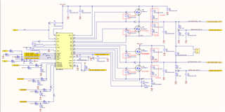
The hardware drives brushed DC to the H-bridge, and the customer would like to know if there is a development timing for SPI similar to DRV8750s-Q1? For example, the timing of initialization, the timing of normal operation, the timing of diagnostics, etc.?
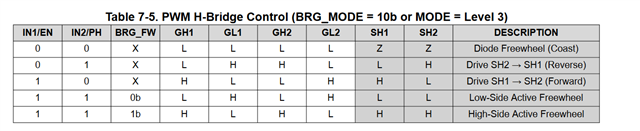
Also, do PWM waves for both IN1 and in2 inputs require complementary waveforms? Does HIZ1 and HIZ2 need to be pull high or low?
Could you please help check this case? Thanks.
Best Regards,
Cherry