This thread has been locked.

If you have a related question, please click the "Ask a related question" button in the top right corner. The newly created question will be automatically linked to this question.

DRV8343H-Q1EVM: Can I use this EVM to test DRV8340H?

Part Number: DRV8343H-Q1EVM
Other Parts Discussed in Thread: DRV8343S-Q1EVM, DRV8343-Q1, MSP430F5529

Hi experts,

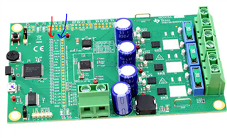
I wonder know if I can use this EVM board to test DRV8340H?
Like directly replace DRV8343H by DRV8340H.
What features do I need to care?

Otherwise, I saw there is a hall sensor pin in EVM.
Does it have hall sensor soldering space on EVM?

How could I accomplish testing by DRV8340H+Hall sensor on DRV8343H-Q1EVM?

BR,

Thank you.

  • Hi Aaron, 

    DRV8340H has no current shunt amplifiers, the equivalent on the DRV8343H would be to tie the inputs (SPx, SNx) together to GND and float the outputs (SOx). Since you are using the Hardware version, you cannot disable the CSAs via SPI. The only way to replace DRV8340H on the EVM would be to:

    1) Cut the input traces SPx and SNx, and blue-wire those traces to GND
    2) Cut the SOx traces so they are floating

    An easier solution would be to evaluate the DRV8343S-Q1EVM, which I still see stock on ti.com. Then in SPI you can disable the CSAs through these registers:


    Then set the settings the customer would use on the DRV8340H, and this should give the equivalent functionality of evaluating a DRV8340H using the DRV8343S-Q1EVM. 

    Thanks,
    Aaron


  • Hi Aaron,

    Thanks for the help. I have some questions.

    1. How to cut the trace from PCB?

    2. After I set the disable of CSAs, does it mean I don't have to change the DRV8343S by DRV8340H on the EVM, then I could use DRV8343S as DRV8340H?


    BR,

    Aaron 

  • Hi Aaron,

    1) Cutting traces on a PCB is using a sharp tool such as a razor, exacto knife, or tweezers to cut the copper trace connection. You would need to cut traces SPx/SNx and SOx near the DRV8343-Q1 IC to split those connections from the rest of their traces. This may be hard to do since the traces are thin and close to other traces, and it is hard to repair those connections once they are broken. 

    2) DRV8340 and DRV8343 have same gate driver architecture, there is no functional difference between the gate drive outputs and configurable settings between devices. The EVM is meant to support DRV8343, not DRV8340, or else you'll have to do the steps from above to make it work without running into GUI issues or getting unnecessary overcurrent faults. If you follow the steps to disable the CSAs and set the same settings the customer would use in Hardware on the DRV8340H, then functionally the DRV8343S will act as the DRV8340H. 

    Thanks,
    Aaron

  • Hi Aaron,

    Happy new year.

    Since my customer didn't have SPI interface.
    Is that possible to read the fault pin without SPI?

    Thank you.

  • Hi Aaron, 

    Happy New Year to you as well. 

    If SPI interface is not used, fault debug is a bit more difficult to determine since the only indication of a fault will be the nFAULT pin going low. In this case, you'll need to use oscilloscope waveforms from ENABLE going high and look at timings and gate driver outputs to determine if the fault could be:
    - VDS overcurrent
    - VGS faults
    - Diagnostic faults (i.e. Open Load passive, open load active, Short to Battery, or Short to GND).

    Thanks,
    Aaron

  • Hi Aaron,

    Since DRV8340H has a build in LDO, but the current of it is only 30mA.

    From your perspective, what devices need this 3.3V/30mA that works with DRV834x?

    On the other words, what will be the surrounded device of DRV834x that need this 3.3V/30mA?
    If I would like to implement 3.3V/30mA for the power of MCU, is that possible to add a current amplifier to boost the current?
    Do you recommend any current amplifier for this case?

    Thank you.

    Aaron

  • Hi Aaron,

    Since DVDD only provides 30mA, external ICs should be minimal on this rail, or else you could overload the LDO and cause LDO undervoltage, which can unpower ICs on the DVDD rail (i.e. an MCU). 

    You could use an external buck or LDO to generate 3.3V from VM. I don't know much about current amplifiers, that may be possible in this configuration. For recommendations, can you start another E2E thread with the appropriate team?

    Thanks,
    Aaron

  • Sure, I will post another E2E thread.

    Just want to confirm, does this DVDD pin be used in DRV8343S-EVM?

    If it is used, does it give a power to MSP430?

    May I have the schematic of it?

    BR,

    Aaron Chen

  • Hi Aaron, 

    Hardware files for DRV8343S-Q1EVM are here: https://www.ti.com/lit/zip/slvc710
    You can find schematic in there called MD005A(001)_Sch.pdf. 

    The DVDD is only used for VSDO (pullup for SDO push-pull driver), which requires less than 5mA current. MSP430 is powered via the USB, which is 5V. The USB powers the FT232RL, which is a USB-to-UART FTDI chip for GUI communication. It has a built in regulator that supplies 3.3V out (3.3V_COM), which is used to power the MCU (3.3V_MCU). This is standard across many of our EVMs that support USB. 

    Thanks,
    Aaron

  • Hi Aaron,

    My customer would like to know does TI have application note of DRV8343S-EVM?
    Since there are only user guide of it, do we have application note?


    Thanks.

  • Hi Aaron,

    These User Guide go in depth on how to use the hardware (EVM user's guide), software overviews, (sensored/sensorless/independent mode user's guide), GUI user's guide. 

    Is there a specific request from customer, i.e. how to use the GUI? I would start with the EVM User's guide on top to begin with. 

    Thanks,
    Aaron

  • Yes, they have some question.

    Since my customer would like to control DRV8343S-EVM with their own MCU.

    They would like to know : 

    Is it possible to disable the EVB MCU? so that they could connect it with their own MCU.

  • Hi Aaron,

    Best way to accomplish this is to depopulate 0-ohm resistors (red arrow) between MSP430F5529 MCU on the EVM and populate the 100-mil header row on the EVM (blue arrow). Then jumper over signals from customer's MCU to the header row. 


    Thanks,
    Aaron

  • Hi Aaron,

    I see, you mean removing the 0ohm resistance.

    Then, soldering 100mile header row in blow row, right?

    The header row that you mentioned is the below things, right?


    From my understanding, removing the resistance will cut the connection of MCU?
    Am I making sense?

  • Hi Aaron,

    Yes, that's correct. Using 0-ohm resistors is common because it's easy to remove the connection without having to break the trace. The headers make for nice test points as well. 

    Thanks,
    Aaron

  • Hi Aaron,

    My customer were testing the DRV8340S-EVM, if they would like to test it in independent MOSFET driver mode, and control by hardware interface.

    May I know how to connect the following 4 pins? 

    BR,

    Aaron Chen

  • Hi Aaron,

    On DRV8343S-Q1EVM, the DRV8343 device is SPI variant and the H/W variant headers are automatically depopulated (see red circles):


    To use the hardware device on this EVM, you'll need to:
    - Replace the DRV8343S-Q1 with a DRV8343H-Q1
    - Depopulate the 0-ohm resistors for the SPI pins (SDI, SDO, SCLK, nSCS) between the MCU and header row: R29, R33, R34, R35  (see blue circle)
    - Add headers for the hardware variant jumpers and use a shunt jumper to connect the correct settings as mentioned in the User's Guide

    In my opinion, it would be easier to just use the DRV8343H-Q1EVM instead since it has everything already configured for the hardware variant of the device. 

    Thanks,
    Aaron


  • Hi Aaron,

    I didn't scribe the question clear.

    At first, I applied DRV8343S-EVM to have a easier way for testing it as DRV8340H-Q1.

    However, their MUC doesn't have SPI interface, just generates 6PWM signal.

    If they would like to pass in 6PWM signal in DRV8343S-EVM to make the fan start rotating as DRV8340H-Q1.

    Is it possible to control like this?
    May I know how to connect the SPI pins?
    Will you recommend to apply DRV8343H-EVM for this testing request?

    BR, thanks

    Aaron Chen

  • Hi Aaron,

    Recall back to the beginning of the thread:

    An easier solution would be to evaluate the DRV8343S-Q1EVM, which I still see stock on ti.com. Then in SPI you can disable the CSAs through these registers:


    Then set the settings the customer would use on the DRV8340H, and this should give the equivalent functionality of evaluating a DRV8340H using the DRV8343S-Q1EVM. 

    Here's what you can do but use the customer's 6 PWM signals from their MCU, instead of the PWM signals from the MSP430F5529:

    1) Populate the header row on the EVM
    2) Depopulate these resistors: R23, R24, R25, R26, R30, R31


    3) Jumper over the customers 6 PWM signals from their MCU to the associated test points on the header row. 
    4) Power on the DRV8343S-Q1EVM and plug into the computer. 
    5) Launch the DRV8343-Q1 EVM GUI. 
    6) Click "Enable" to set the ENABLE signal high and enable the SPI logic. 
    7) Set the SPI settings in the "Registers" tab to the same that the customer would like to set in DRV8340H-Q1. 

    IDRIVE pin --> IDRIVEP_HA, IDRIVE_HB, IDRIVE_HC, IDRIVE_LA, IDRIVE_LB, IDRIVE_LC
    MODE pin --> PWM_MODE
    VDS pin --> VDS_LVL_HA, VDS_LVL_HB, VDS_LVL_HC, VDS_LVL_LA, VDS_LVL_LB, VDS_LVL_LC

    You can disable the VSEN_OCP faults from the CSAs by setting DIS_SEN_A, DIS_SEN_B, DIS_SEN_C to 1

    After these steps, you should be able to spin the motor using 6x PWM signals and hall sensors externally. This should be the same operation as DRV8340H-Q1, you should be able to ignore the CSA outputs. Recall that this method is the most ideal, since the other method would be to use DRV8343H-Q1EVM and cut the CSA input/output traces and tie the inputs to GND. 

    Thanks,
    Aaron

  • Hi Aaron,

    Thanks for the prompt reply, you are a hardworking and outstanding man.

    For hardware aspect, only six pins need to be changed to connect to their own MCU PWM output pin.
    For firmware aspect, disable the CSAs and setting the mode/IDRIVE/VDS pin is required.

    Am I making sense?

    BR,

    Aaron

  • Hi Aaron,

    Yes, this should work from a hardware and firmware aspect. Thank you. 

    If the GUI runs into any software overcurrent limit faults due to the CSAs outputs, we can figure out which settings in the GUI we can toggle to get rid of those so there are no dependencies on the CSAs in the DRV8343-Q1, which would make performance similar to DRV8340H-Q1. 

    Thanks,
    Aaron

  • Hi Aaron,

    As the User's guide shows, may i know where can I get the DRV8343-Q1x-0.1.0_EVM_GUI.exe?

  • Hi Aaron,

    The GUI should be in the Firmware folder on the EVM page. I linked below.

    FIRMWARE

    DRV8343S-Q1 EVM Firmware (Rev. A) 

    Thanks,
    Aaron

  • Click "Enable" to set the ENABLE signal high and enable the SPI logic. 
    7) Set the SPI settings in the "Registers" tab to the same that the customer would like to set in DRV8340H-Q1. 

    IDRIVE pin --> IDRIVEP_HA, IDRIVE_HB, IDRIVE_HC, IDRIVE_LA, IDRIVE_LB, IDRIVE_LC
    MODE pin --> PWM_MODE
    VDS pin --> VDS_LVL_HA, VDS_LVL_HB, VDS_LVL_HC, VDS_LVL_LA, VDS_LVL_LB, VDS_LVL_LC

    You can disable the VSEN_OCP faults from the CSAs by setting DIS_SEN_A, DIS_SEN_B, DIS_SEN_C to 1

    Hi Aaron,

    After my customer click "enable", where can I set the step 7?

    BR,

    Aaron Chen

  • Hi Aaron,

    In the registers tab on the left. 

    Thanks,
    Aaron

  • 2) DRV8340 and DRV8343 have same gate driver architecture, there is no functional difference between the gate drive outputs and configurable settings between devices. The EVM is meant to support DRV8343, not DRV8340, or else you'll have to do the steps from above to make it work without running into GUI issues or getting unnecessary overcurrent faults. If you follow the steps to disable the CSAs and set the same settings the customer would use in Hardware on the DRV8340H, then functionally the DRV8343S will act as the DRV8340H. 

    Hi Aaron,

    Could I remove R42, R43, R44 in stead of cut the trace on the PCB?

    Then use Hall sensor and connect it on J6 to act it as a DRV8343H with Hall sensor control? 

    BR,

    Thanks

  • Hi Aaron,

    Yes, you can remove R42, R43, and R44 to float the CSA outputs (SOx). I think SPx and SNx are not bonded out in DRV8340H (these are NC pins) so all you need to do is remove the resistors and replace the IC with DRV8340H to act it as a DRV8343H. 

    You can connect the Hall sensors to J6 to use with Hall sensor control. The Hall commutation will come from the MCU and GUI, unless you configure the EVM and MODE pin for 1x PWM mode. 

    Thanks,
    Aaron