This thread has been locked.

If you have a related question, please click the "Ask a related question" button in the top right corner. The newly created question will be automatically linked to this question.

DRV8432: driver burning.

Part Number: DRV8432

Hi TI support.

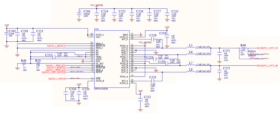
I use DRV8432 to drive motor 0.24mH, 1ohm coil.  My configuration:

- Parallel Full Bridge Mode Operation.

- 500KHz PWM frequency.

- 4.7uH inductors installed on each output before connection two channels together.

- 2.2uf capacitors connected to ground from these connection points (for filtering out PWM frequency).

Is it OK to have these capacitors? No such capacitors in application examples to drive inductive load in the data sheet. Such capacitors shown for non-motor related applications (for example, resistive load or dc output).

Can those capacitors be the reason for DRV8432 burning?

Thanks,

Sergey

  • Hi Sergey,

    Can you share a schematic of what you are trying to do. I think I have a good idea of what you are trying to do but to make sure we are on the same page, I would like to look at the schematic.

  • Hi Pablo,

    Thank you for prompt response.
    Please, see the schematics. I’m talking about C272, C273 capacitors. On the schematics shown 1uF, but recently replaced with 2.2uF. It looks like 2 boards burned after this replacement. Is it possible?

    Thanks,
    Sergey

  • Hi Sergey,

    I don't see a problem with the capacitors placement location.

    Can you provide more detail on the damage. Was the IC physically burnt? Can you sent a picture of the burnt IC?

  • Hi Pablo,

    Please, look at picture. Current limit was set to 10A on controller side.

  • Sergey,

    Thanks for sending the picture. The highlighted pins below are the ones that got burnt. Basically almost all of the pins that are damaged are power supply and output pins. So this makes me hypothesize that the there might have been a short or a big current spikes in the power supply. The 12V VDD supply looks to be the culprit here since the VDD and GVDD_C pins on the left side are also damaged.

    Was the IC getting damaged when the output capacitors 1uF? Did this issue only occur AFTER changing the capacitance to 2.2uF? If so, let's focus our troubleshooting on this capacitor.

  • Hi Pablo,

    We have two damaged ICs, both after changing capacitors to 2.2uF. We found spikes in measured current for feedback. 2.2uF helped with those spikes.

  • Another problem we are experiencing is a driver fault. It happens not often, so it's hard to capture on the scope. With current limit set to 10A (27K resistor to OC_ADJ) we are getting driver fault while driving not more than 2A current (we constantly monitoring current in our controller).

  • Hi Sergey,

    I have one more question. What is the PWM duty cycle? I know the frequency is 500kHz which is at the upper limit of this device.

    To deal with the pre driver fault, please set the TDRIVE to the maximum value. This should help.

  • Hi Pablo,

    1.  PWM duty cycle from 20% to 80% of PWM period (2uS). 20% (400nS) is min pulse width and 80% (1600nS) is max pulse width.

    2.  What is TDRIVE and "pre driver fault"? I mentioned DRV8432 FAULT signal, which could be active for no visible reason.

  • Hi Sergey,

    What is TDRIVE and "pre driver fault"? I mentioned DRV8432 FAULT signal, which could be active for no visible reason.

    Forgive me. I was confusing this device with another one of our gate drivers. Please disregard this comment. When the fault occurred, did it latch requiring a device reset to resume operation?

    1.  PWM duty cycle from 20% to 80% of PWM period (2uS). 20% (400nS) is min pulse width and 80% (1600nS) is max pulse width.

    This is fine. The minimum pulse should be ~50ns or so. Anything lower than that and the device may not work properly.

  • Hi Pablo,

    1.  Is any gap between PWM_A and PWM_B pulses required or edges can be aligned?

    2.  When the fault occurred it latched and device reset required to resume operation.

  • Hi Sergey,

    1.  Is any gap between PWM_A and PWM_B pulses required or edges can be aligned?

    No gap is required, the driver will automatically insert a dead time while H-bridge is transitioning states to prevent both FETs of a half-bridge from conducting at the same time.

    2.  When the fault occurred it latched and device reset required to resume operation

    Most likely, the fault was cause by an over-current event as you can see on the table below. It's very difficult to determine if this fault has any relation to the damage on the IC as it's not repeatable.

    Please give me 24 hours to really think about this and provide suggestion for troubleshooting.

  • Hi Sergey,

    Can you tell what pcb copper thickness you use, what is VCC_Motor voltage and if you use both sides of pcb for component placement?

    In the past analog audio power amplifiers were used to control galvos so maybe D-class amplifier design might be useful in your case.

    For output filter design filter on page 34 of below mentioned TAS5634 datasheet may be a good start point, just bandwidth should be adjusted to your needs.

    https://www.ti.com/lit/ds/symlink/tas5634.pdf?ts=1642094747702&ref_url=https%253A%252F%252Fwww.ti.com%252Fproduct%252FTAS5634

    Regards,

    Grzegorz

  • Hi Grzegorz,

    Cannot tell you right away pcb copper thickness, PVDD voltage for motor driving is 48V. Component placed on both sides (inductors L6, L7 are on the bottom side). 

    We prefer to use switching amplifiers for less heat dissipation.

    Filtering capacitors C272, C273 (especially 2.2uF) could be the problem. Excessive current flow through those capacitors and can reach a few amps. Probably this current (with load current) can trigger fault sometimes. 

    Without capacitors driver report fault if low inductance/impedance motor connected.

    Thanks,

    Sergey 

  • Hi Sergey,

    Thanks for your answer. Two possible failure causes come to my mind.

    - if copper thickness is 35um (1oz) high current traces can experience overheating and damage, 48V is quite safe for 0.65mm pin distance so that should not be the problem.

    - DRV8432 is a very fast Mosfet based driver (14ns fall/rise times) and using it at 5A I would expect problems with ringing and overshoot/undershoot of voltages caused by parasitic inductances. These voltage spikes/ringing can damage IC. To limit that I would keep length of traces to minimum (every 1mm matters). Looking at your pcb I noticed that bootstrap caps C228 and C231 are far away from IC pins (high inductance), traces between decoupling caps C223,C227,C225, C226 and IC pins are thin (again high inductance), caps C219, C220, C222 and C218/C221 could be placed a bit closer to IC and their GND traces should be much wider and connected to ground plane with ground vias. These are just 3 examples of possible problems and areas to improve.

    I guess it would be much easier for you to use DRV8432EVM board as a design start point (I went that way in case of another ic driver and it worked well for me).

    https://www.ti.com/lit/ug/slou291a/slou291a.pdf?ts=1642070424031&ref_url=https%253A%252F%252Fwww.ti.com%252Fproduct%252FDRV8432

    I think it is very well designed board, if components could be placed on the back of pcb I would just place bootstrap caps C18 and C20 (Figure 4) on the back of pcb and as close as possible to IC pins.

    Of course, even well designed board does not guarantee the circuit will work.

    Regards,

    Grzegorz

  • Hi Grzegorz,

    Thank you for response.

    - High current traces are not overheating, I think copper is 2oz.

    - I already thinking to redesign the board, and will follow your suggestions.

    - In parallel mode should current limit be twice more (with 27K OC_ADJ resistor limit will be 9.7A*2= 19.4A)?

    - OC protection detect pic current (response time 250nS according to specs)?

    -My concern now filtering capacitors C272, C273. Current through capacitors 2.2uF can reach like 8A, plus load current (3A). Still should not trigger OC, but it does sometimes. 

    Regards,

    Sergey

  • Are driver inputs PWM_A and PWM_B protected against glitches due to interference?

  • Hi Sergey,

    I said that 48V is quite safe for 0.65mm pin pitch (maybe it should be coated to meet some standards) but I thought about well made soldering. Solder joints on the bottom of burned IC do not look well, maybe it is caused by light or camera angle but I think it would be worth to check them under microscope. Any extra solder between pads/pins may increase a risk of short circuit.

    "- In parallel mode should current limit be twice more (with 27K OC_ADJ resistor limit will be 9.7A*2= 19.4A)?

    - OC protection detect pic current (response time 250nS according to specs)?"

    I know DRV8432 only from datasheet but I guess 19.4A is right, at the beginning of datasheet 24A peak current is mentioned for parallel mode. According to table 6.7 "Time from application of short condition to Hi-Z of affected FET(s) = 250ns" , it is typical time and I guess it could be significantly shorter or longer.

    I think loosing 70% of output current to filter is not a good usage of driver current capacity. Could you tell approximately what is minimal motor inductance you need to drive, output bandwidth and peak current? If it is let's say 100uH motor at 40kHz BW and 15A peak then I think design will be challenging.

    Regards,

    Grzegorz

  • Hi Sergey,

    In parallel mode should current limit be twice more (with 27K OC_ADJ resistor limit will be 9.7A*2= 19.4A)?

    This is correct but you also need to take into account the temperature rise. At such high currents, the over-temperature fault may trigger before the OC fault. Make sure to have proper heatskink to dissipate the heat.

    - OC protection detect pic current (response time 250nS according to specs)?

    This is the typical value and there can be slight differences from IC to IC due to component tolerances. But the typical value is 250ns. This is something I also forgot to mention previously. If the current goes above the OC limit and last for less than 250nS, the device will be damaged before the OC fault is triggered.

    -My concern now filtering capacitors C272, C273. Current through capacitors 2.2uF can reach like 8A, plus load current (3A). Still should not trigger OC, but it does sometimes. 

    Have you taken waveforms of the current when an OC fault occurs? Due to PWM switching, there can be large current spikes which can go above OC limit. If you take a current waveform and zoom in near the area when nFAULT drops LOW, you should be able to see the current spike.

    Are driver inputs PWM_A and PWM_B protected against glitches due to interference?

    I'm not sure what you are asking here but the driver will add a dead time (time where all FETs are disabled) when H-bridge is switching states. So precise PWM synchronization is not required.

  • Hi Grzegorz,

    Now we have another 3 ICs burned. No visible damage, but outputs shorted to ground internally. The motor we drive is 6ohms\2.4mH coil, 8A peak current. Looks like the problem begun after we replaced capacitors C272, C273 with 2.2uF (from 1uF). Bandwidth is within 10KHz.

    Another motor we drive is galvo 1ohm/0.24mH, 10A peak current. One burned IS (picture we sent to you). 

  • Sergey,

    Thanks for your response.

    Looks like it is not a very demanding design and I think there is a good chance DRV8432 will be OK. I think it is safer to start with designs that already work. I would try to use DRV8432EVM for a pcb design and TAS5634EVM for a filter design (not only L and C values but also caps and inductor types - more linear), then if there are problems I would try to find a solution.

    Other way would be to try analyze and debug your current board (maybe after coming back to 1uF caps),checking if there is any ringing and switching noise on IC outputs and supply pins, current regulation circuit if it is fast enough, its stability etc. I think you would need at least 2-channel oscilloscope 60-100MHz or faster, probes with ground springs and current probe. Some cheap probe like https://www.amazon.com/Hantek-CC-65-Multimeter-Current-Connector/dp/B06W2KFZLW  might be good enough to monitor motor current.

    Design files for TAS5634EVM :

    https://www.ti.com/tool/TAS5634EVM#design-files

    Regards,

    Grzegorz

  • Hi Pablo & Grzegorz,

    First about current design. You think 2.2uF capacitor could be the matter? Should be almost no difference in current at 500KHz: inductor impedance is 15ohms, 2uF is 10 times less (0.15ohm), 1uF is 0.3ohm, so current limited by inductance. At lower frequencies capacitors impedance will be significant (80 ohms/160ohms at 1KHz). Cold be something related to motor inductance?

    Thanks,

    Sergey

  • It looks like in our application impossible to burn driver at all. 48V power supply can drive only 8A through 6oms motor, drivers max current is 14A continuous. No overheating flag. In case it shorted to ground externally (outside the board), 4.7uH inductance will insure overcurrent protection will save the device. 3 drivers shorted internally with no visible damage (meaning no short circuit on the board). How came?

    I have checked overshoots on driver outputs: not higher than 55V.

    Thanks,

    Sergey

  • Hi Sergey,

    I think 2.2uF in output filter is to much if you need to move motor shaft up to frequency of 10kHz. To be able to control movement of motor shaft at that frequency I think you would need BW of current loop around 50kHz. To control motor current at 50kHz you would need to be able I guess to change voltage at motor terminals even faster. That voltage is also present on C272 and C273. Impedance of 2.2uF at 50kHz is 1.45Ohm, at higher frequency it will be even lower while motor impedance for 2.4mH at 50kHz is 754Ohm. That means that nearly all current at 50kHz that menages to pass filter inductors will return through filter caps. Now I think the only filter that can be placed between driver and motor for that kind of BW is EMI filter but not PWM filter.

    "Should be almost no difference in current at 500KHz" - that is true, but you would need to operate from DC to 50kHz or more. If we added a few micro Farads more we would get quite decent DC/DC buck converter.

    "48V power supply can drive only 8A through 6 oms motor" - that is true for motor at standstill (no BEMF) and DC current. AC current will also flow through LC filter and can be really high unless you control current PWM cycle by cycle. There is also some small chance that LC filter will go into series resonance and then its impedance would be close to zero.

    "4.7uH inductance will insure overcurrent protection will save the device" - if circuit is well designed then it should be true. In case of not optimal design voltage transients (u =  L di/dt) caused by parasitic inductances and high di/dt may damage driver.

    "3 drivers shorted internally with no visible damage (meaning no short circuit on the board). How came?" - I mentioned possible cause in previous post.

    "I have checked overshoots on driver outputs: not higher than 55V." - can you share waveforms and how you did it? Its very important what was the driver output current at time of the overshoot, the higher current the higher transients. Using ground springs is necessary for single ended probes to minimize picking up electromagnetic noise. BW of oscilloscope and probes should be significantly higher that transients/ringing frequency, otherwise measured amplitude correction is needed. Usually more dangerous than overshoots are voltage undershoots. Frequency of ringing probably in most cases is somewhere within 50 - 150MHz, in case of my board it is around 110MHz.

    Together with overshoot waveforms I would also take waveform of voltage on C272/C273, if you do not have quite high speed current probe to measure driver output current then C272/C273 current can be estimated with du/dt.

    All above are just my thoughts and I may be wrong in some cases.

    Regards,

    Grzegorz

  • Hi Grzegorz,

    With 48V power supply driver cannot drive high current at high frequencies through 6ohms\2.4mH motor. At 1KHz in can drive sinewave 5A p-p before it saturated. Please, look at picture below. Setup: 2.2uf cap, sine wave current 4A p-p at 1KHz through the load. Dark blue is current measured with current probe from OUT_D (pin 22) , light blue is load current measure with sense resistor (2V/1A), yellow voltage on C272. Almost no difference with 1uF cap. Single output current is 6A p-p.

    Overshoots with same setup (red is voltage on UOT_D):

    Same setup, but 4KHz sinewave (1.3A p-p load current, 6.8A p-p single output current):

    Overshoots within markers:

    Anything wrong with our setup? We never force driver to saturation (constantly monitoring current loop error). 4 drivers somehow shorted internally.

    Thanks,

    Sergey

  • Hi Sergey,

    Thanks for posting all waveforms.

    First waveforms from the top look very clean.

    Second waveforms, zoom was taken when motor current is close to zero, driver output current is symmetrical to zero value (I guess C6 is 0 marker). Ringing amplitude is not really high but current during switching is only +/- 2.1A, the higher current the higher ringing amplitude will be.

    Third waveforms from the top. Voltage on C272 contains ringing at around 50-60kHz, just after voltage half-sinusoid ends we can also observe significant driver output current ringing at the same frequency. The ringing is not present on motor current so it occurs only in driver and LC filter area. LC filter resonant frequency for 2 inductors in parallel should be around 70kHz so there is a good chance that ringing is caused by LC filter series resonance, if resonance develops further it may increase current ringing amplitude several times so current reaches value high enough to trip OC protection at 9.7A. Current at 9.7 A per pin will cause much higher undershoots/overshoots that are seen on waveforms second from the top and bottom one and may damage driver.

    Last waveforms were taken when 50-60kHz driver output current ringing is present, max driver output current value is around +3.8A, undershoots are larger than previous ones at +2.1A. It would be good to zoom these undershoots and check if their amplitude is not higher.

    If my theory is right capacitor change from 1uF to 2.2uF may cause problems with resonance, increased ringing and driver damage.

    Is 4kHz the highest motor current frequency you use?

    Links below may be useful:

    https://www.ti.com/tool/LCFILTER-CALC-TOOL

    www.ti.com/.../slaa701a.pdf

    Regards,

    Grzegorz

  • Hi Grzegorz,

    On the second waveform all overshoots/undershoots are within white cursor lines. I assume they could be bigger at some conditions. What is max undershoot (0.3V looks very strict)?

    Ringing at higher frequencies present for both caps, just at different frequencies. Please look at waveforms. 

    This is not real conditions, just use sine wave to check at different frequencies with no driver saturation, but bigger possible current.

    1uF, 4KHz, 4A p-p load:

    2.2uF, 4KHz, 4A p-p load:

    1uF, 10KHz, 0.65A p-p load:

    2.2uF, 10KHz, 0.65A p-p load:

    I tried to overload driver with 6ohms\2.4mH motor connected, but was not able to (used sine wave at different frequencies wit max amplitude, even heavy saturated driver, but driver cannot drive high enough current to generate fault). So, still two questions:

    1. How we are getting faults sometimes?

    2. 3 drivers shorted internally (undershoots?). Output trace inductance will not increase dI/dT, OC protection should work.

    Thank you,

    Sergey

  • Hi Sergey,

    In my design based on another driver I was operating prototype board with 10-12V undershoot a couple of ns wide (half-sine of 100Mhz) for a couple of weeks/months with no problems. After trying some tricks to minimize parasitic inductance I managed to limit these undershoots to around 5 V, frequency of ringing increased to around 110Mhz. So far I have not experienced any problems with couple of boards working from a couple of days to around 1.5 year. 5V is still much higher than 0.6V allowed by datasheet in my case, I would call it an "operating in grey area". I blew a few driver ICs and Mosfets because of transients but I did not verify what was their level at that time, I guess a bit higher than 12V. I am not able to say what level of transients is safe for your design.

    First two waveforms look very good to me but the last two look really bad. Frequencies of ringing, around 90kHz and 67kHz just support my theory about series resonance.

    "I tried to overload driver with 6ohms\2.4mH motor connected, but was not able to (used sine wave at different frequencies wit max amplitude, even heavy saturated driver, but driver cannot drive high enough current to generate fault). So, still two questions:"

    I do not think motor current is a problem, on waveforms above it behaves well. The problems are probably caused by LC filter and driver output currents that contrary to motor current are much higher and behaves unpredictable. It is driver output current that can trip OC protection and is responsible for transients (undershoot) level (L di/dt).

    "1. How we are getting faults sometimes?" - if it is OC fault, then series resonance of LC filter is my suspect number one, of course I can be wrong.

    "2. 3 drivers shorted internally (undershoots?). Output trace inductance will not increase dI/dT, OC protection should work." - if damage was caused by undershoot (I guess the most common killer of drivers) then OC protection could not save the driver. I think undershoots can cause physical damage to IC structure or disrupt internal IC logic leading to cross conduction and catastrophic damage. OC protection is designed to protect driver against overcurrent and shorts when any inductance from driver to short (including output trace inductance) helps to slow down rise of current and finally its max value.

    Parasitic inductances in ground, power supply and bootstrap circuits are completely different story, they do not help to limit problems but they are causing them. 

    Voltage undershoots/ overshoots and that possible series LC filter resonance are the only potential problems that I could find, of course problems can be caused by something else.

    First I would try to eliminate ringing caused probably by resonance. Changing values of L and C, types of capacitor/ inductor and adding some lossy parts (containing resistor) may help solve that problem. I would try to increase filter inductance a bit to limit current amplitude seen on last waveforms from your previous post.

    If PWM switching noise causes problems with current measurement then maybe filtering signal from sense resistor would be a better option than filtering PWM signal (lower levels of power to deal).

    The next thing would be redesigning pcb the way I mentioned a few posts earlier. 

    EVM board and note below would be a good start point.

    www.ti.com/.../slva959b.pdf

    Regards,

    Grzegorz

  • Hi Grzegorz,

    Thank you for response.

    1. I measured IC output current with closed loop and found short high current spikes possible. I assume intermittent faults are possible with 2.2uF and more aggressive loop setup. Ringing could be the problem.

    2. The calculator you send gives capacitor value should be 0.22uF. Will try to reduce ringing.

    3. I think spikes on the current sense resistor could be due to resistors inductance. High speed transitions will generate spikes across resistor. In this case reducing capacitor will, probably, reduce ringing but make spikes even bigger.

    Sergey

  • Sergey,

    No problem.

    "3. I think spikes on the current sense resistor could be due to resistors inductance. High speed transitions will generate spikes across resistor. In this case reducing capacitor will, probably, reduce ringing but make spikes even bigger."

    Sense resistor inductance plays a big role in case of LS and probably HS sense resistors but I think it should not cause additional HF noise in case of inline sensing. I guess all high frequency noise like undershoot/overshoot ringing (something around 20-25Mhz in your case) comes from driver alone and pcb parasitic inductances. If that noise is the problem then limiting parasitic inductances would have additional benefit, it would increase its frequency, lower its amplitude and made it easier to filter out. Filters based on Common Mode Chokes and ferrite beads are quite effective against HF noise but probably are not good to filter PWM wave at 500kHz.

    If you could show waveform of that sense resistor noise, ideally together with driver output voltage, I might be able to suggest what type of CMM choke to try.

    In case of PWM noise at 500kHz maybe current sense amplifier like INA240 would be good.

    Regards,

    Grzegorz

  • Hi Grzegorz,

    I think all my problems caused by LC filter oscillation. With  4.7uH/2 inductors and 1uF capacitor it oscillates on 100KHz (as calculated resonance).

    Below waveform with closed loop.

    Light blue - load current, dark blue - IC output current (single output), yellow - cap voltage:

    How to reduce oscillation? Is it possible on current board (increase inductance)?

    Thanks,

    Sergey

  • Hi Sergey,

    I would try to increase L lets say to 10uH and see what will happen, driver current amplitude during normal work should be lower but its hardly to say what will happen with oscillations.

    I would try to lower Q factor of LC filter by adding some lossy components to the circuit. If oscillations frequency was around 1Mhz or more then CMM choke with sectional winding and Mn-Zn core might work but at 100kHz probably it would not.

    I would try to add in parallel to C272 and C273  resistor+capacitor in series, I would try resistor values from around 1 Ohm to 10 Ohm and capacitors from 1uF to 10uF. I would start with resistors of higher values and smaller caps.

    Another method would be to add power resistors in series with inductors, something around 100-220 mOhm may help but it would increase power losses.

    I would try types of inductors (Toroid, Powdered Iron) and caps for C272/C273 (film capacitor) used in https://www.ti.com/tool/TAS5634EVM#design-files.

    During tests I would monitor driver output current and oscillations in case they get larger.

    Regards,

    Grzegorz

  • Hi Grzegorz,

    Thank you for advice, I've ordered 13uH inductors (will be 6.5uH in parallel). Will try to play with capacitors.

    Will let you know results. Anyone else experiences same oscillation problem (could not find on the forum)? I don't see anything completely wrong in our design.

    Thanks again.

    Sergey

  • Hi Grzegorz,

    Thanks for sharing your expertise with us on this post. I think you conclusion that the LC filter is the culprit make sense.

    Sergey,

    It seems like the next steps for you will be to work on modifying the LC filter to minimize those spikes.

    Let us know once you get some results with the new LC filter.

  • Hi Pablo and Grzegorz,

    Thank you for help. I will let you know as soon as I get results.

    Sergey