This thread has been locked.

If you have a related question, please click the "Ask a related question" button in the top right corner. The newly created question will be automatically linked to this question.

BOOSTXL-DRV8304H: Why the mosfet is burned after a software problem?

Part Number: BOOSTXL-DRV8304H
Other Parts Discussed in Thread: DRV8304

Hello,

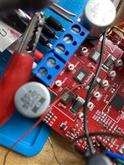
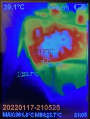
I have experienced a very bad moment, I was working to tune the PID Controller in my algorithm and suddenly I have seen smoke and some lighting on the MOTC Mosfet.

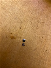
I removed my source and I have seen that Mosfet C and shunt resistor are broken. Mosfets are shorted and shunt resistor is open circuit.
My expectation was that Vds and Vsens process should protect my Mosfets from the disaster.
My supposition is that after a stack overflow the variables with the ADC Data are overwritten and after that the output is very high and creates a short circuit.( maybe a shout through or Dutty cylces around 100% or 0%)

The High and Low Mosfet are both shorted  and the board damaged.

Could u explain it? Why Vds protection or Vsens are both not able to protect the Mosfets?

King Regards,

Nikos

  • Hi Nikos,

    On the DRV8304H, the following settings are defaulted:

    VDS_OCP = VDS pin setting
    VSEN_OCP = 1V
    Tocp_deg = 4.5us
    OCP_MODE = 4-ms auto retry

    IDRIVE = IDRIVE pin setting
    MODE = MODE pin setting
    GAIN = GAIN pin setting

    MOSFET 1/2 bridge block have Qgd = 26nC, so I would ensure IDRIVE settings are not beyond 100-200mA to turn on MOSFETs not too quickly at higher currents. FET used on the 

    Can you please share:

    • What voltage/current you are trying to use with the BOOSTXL-DRV8304H?
    • What MODE you are using?
    • What your IDRIVE pin settings are?
    • What your VDS pin settings are?
    • What was the state of the motor when the software problem occurred, i.e. spinning or starting/stopping?
    • Do you read the nFAULT pin and take any protective actions when a fault occurs, i.e. turning PWMs off and/or ENABLE low?

    Thanks,
    Aaron

  • Hi Aaron,

    I use the default settings. My voltage is 12 Volt. 

    The Motor is spinning and I am pretty sure a stack overflow occures. After the overflow, the software sends an unknown request, after that shunt resistor starts to catch fire and after some miliseconds MOSFET and Shunt resistor are destroyed. nfault Pin didn’t engage and the error was not registered from the drv8304 side. 
    Because both of the mosfets in MotC are shorted, I think it is a shout through situation. 

    it‘s difficult to debug because mosfets catch fire. Now I have repaired the board but if the board will be destroyed again, then I don’t have the possibility  for a new repair. 

  • Hi Nikos, 

    For default settings, do you mean you use BOOSTXL-DRV8304H without any modification before running the motor?

    Looking at the EVM files, I see these settings:

    • IDRIVE = Hi-Z = 90mA/180mA source/sink
    • MODE = 47k to GND = 3x PWM mode
    • GAIN = 47k to GND = 10 V/V

    Do the settings above confirm your expectations?

    When you try eval again, can you set IDRIVE to a lower setting, i.e. remove R16 and R23 = 0-ohm or 18-kohm to GND? Also please unload the motor or use a smaller scale motor to spin the motor and evaluate other features (i.e. CSAs) before running larger power applications to avoid fault conditions. Also, can you please monitor VDS voltages when running the motor to ensure the FETs are not turning on too fast (100-200ns minimum rise/fall time). These precautions will help prevent damage and increase fault protections during motor evaluation. 

    Thanks,
    Aaron

  • Hi,

    yes, I use the BOOSTXL-DRV8304H Device without any modification.

    On the following picture I have monitored the MOTC pin, it seems not so fast. If I see correctly, it needs more than 500ns to transit from ground to VM.

  • Hi Nikos,

    VDS slew rate seems fine, thanks for sharing.

    Another thing is the dead time is automatically set to 120ns in the H/W device. Does inserting more MCU dead time help? If MCU dead time is longer than 120ns, gate driver output dead time will the MCU dead time. 

    Can you measure the following signals with respect to GND see how the gate drivers are operating to see if there is proper gate driver switching?

    • GHx
    • SHx
    • GLx
    • SPx

    I want to ensure the gate drive turn on/turn off waveforms look good, showing the Miller plateau and the correct dead time in the application for the phase that causes issues. Please zoom in to show VGS of the HS and LS MOSFET. 

    Since 3x PWM mode is used, are you giving INLx = 1 and INHx = High or Low to switch the FETs? 

    Thanks,
    Aaron

  • Hi, for the measurements I need some time and now here is 24:00 so I cannot post it today.

    I dont use dead time from the uC, because I knew that drv has dead time configuration.

    I use PWM on INHx and always INLx is high, so the SHx pin toggles between H/L according the PWM Signal.

  • Okay, 

    Thanks for clarification. It seems from when the SW ran into an unknown condition, there was a large amount of current going through phase C LS MOSFET for a long time and caused the shunt resistor to fail, then the FET failed from a shoot through condition if the body diode was recirculating the current. Regardless, it may be difficult to diagnose if the SW condition is unknown. 

    Thanks,
    Aaron

  • Hi, ok I will try to find out the problem exactly. Could you explain me why DRV8304 cannot protect the Mosfets? 

    should  Vsens recognize that too much current is flowing the shunt resistor or not?  

    PS. I have marked this topic accidentally as resolved, could you fix it?

    Thanks, 

    Nikos

  • Hi Nikos,

    The shunt on the EVM is 7mohm, 3W rating. So for 1V to trip VSEN_OCP, we would need to dissipate over 100A across it for longer than 4.5us. It's possible that the shunt failed if such a condition happened for 1 to 4 us before VSEN_OCP could trigger due to the 3W power rating. Again, it is hard to tell exact root cause without waveforms or known behavior of the inputs when the software malfunctioned.


    Thanks,
    Aaron

  • Hi Aaron,

    The resistor has been spited into 2 pieces and my thermocamera has caught about 361 Celsius. 

    I think the current it's more than 100 Amperes.

    Thanks,

    Nikos

  • Hi Nikos,

    That is very high temperature for the shunt resistor. BOOSTXL-DRV8304 is not recommended to be used above 15-A.

    Thanks,
    Aaron

  • Hi Aaron,

    I know it and it is not my normal operation, this temperature has caught after the false condition and unknown behavior of the software.

    thanks,

    Nikos

  • Hi Nikos,

    To resolve this, can you please help determine the software issue that caused this? One thing you can do if you want to confirm that the behavior of the DRV8304 overcurrent protection works correctly for VSEN_OCP is to apply >1V across the shunt resistor (if you haven't replaced it yet) while turning on the associated INLx for the phase. When INLx goes high, the associated shunt for that phase (phase x) will monitor VSEN_OCP. 

    Thanks,
    Aaron