Because of the holidays, TI E2E™ design support forum responses will be delayed from Dec. 25 through Jan. 2. Thank you for your patience.

This thread has been locked.

If you have a related question, please click the "Ask a related question" button in the top right corner. The newly created question will be automatically linked to this question.

DRV8304: Problem with phase waveform in 1x PWM mode

Part Number: DRV8304

Hi,

I am running my DRV8304S on 1x PWM mode.

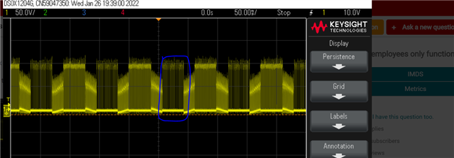
The phase waveform is a perfect trapezoid when DIR=0 (INHC input). When DIR=1, the waveform looks like this:
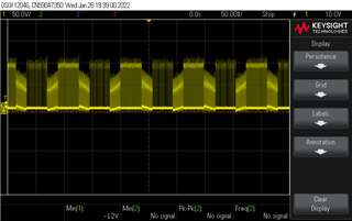
As you can see, there are some stray PWM signals in between the trapezoids.

The input PWM signal (on the INHA line) is 25kHz, and even when I change the duty cycle across the whole range, I find these stray PWM signals.

What could have gone wrong? I do not think it is a board or firmware issue, since everything works just as expected for DIR=0. The only change that causes this is toggling a GPIO, setting INHC to 1.

Is there some configuration I can do with the DRV registers to deal with this?

Thanks and regards,

Vishnu Venkatesh

  • Hi Vishnu,

    What IDRIVE settings and MOSFETs are you using on your board? Can you lower your IDRIVE to a smaller value to see if it improves performance? Follow this E2E FAQ for recommendations on the best IDRIVE setting for your device: https://e2e.ti.com/support/motor-drivers-group/motor-drivers/f/motor-drivers-forum/796378/faq-selecting-the-best-idrive-setting-and-why-this-is-essential

    Is 1PWM_COM = 1b? If so, can you set this to 0b? 

    Thanks,
    Aaron

  • Hi Aaron,

    Thanks for the quick reply.

    I'm using NVMFS5C423NLAFT1G MOSFETs.

    After your recommendation I tried lowering all four IDRIVE settings to the second-lowest values (the lowest gave me gate drive faults): 45mA for IDRIVEPs and 90mA for IDRIVENs. The link you gave me was quite illuminating, I calculated that 33mA would be enough for a rise time of 200ns.

    1PWM_COM was set to 0b, the default. I confirmed this by reading the register during operation.

    However, the problem still persists.

    Would you have any other suggestions on how to proceed? Please let me know.

    Thank you for your help.

    Regards,

    Vishnu

  • Hi Vishnu,

    Can you please probe GHx, SHx, and GLx as well (zoomed in to the SHx outputs that go high between Hi-Z phases) to see if the gates are turning on when SHx goes high? Please zoom in to capture one period of SHx turning on abonormally with GHx and GLx as well.


    Does this occur when motor is loaded or unloaded? Does this happen across all duty cycles or just a certain range?

    Thanks,
    Aaron

  • Hi Aaron,

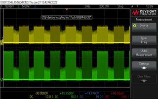
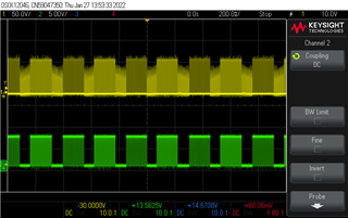
    The gates are turning on when SHx goes high when it's not supposed to. I am attaching a picture here of the SHx line in yellow and GHx/GLx lines in green.

    This is what GHx looks like:

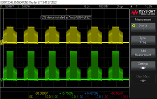
    Zooming into the spurious GHx PWM gives me this:

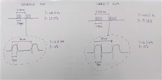
    It looks similar to the correct PWM (i.e, the "on" part of the trapezoid) but with lower frequency.

    I zoomed in to the region you had circled in your reply, and am attaching an illustration of the PWM I saw. I did the same for the 'correct' PWM on the other side of the Hi-Z phase just for comparison. Not really sure if this info is useful, I couldn't see a pattern, but do let me know if you notice something.

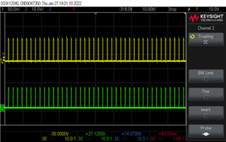
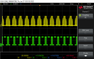
    Probing GLx gave me this:

    The GHx and GLx for DIR=0 appear to be correct, but I'm attaching it just to be fully sure.

    The motor is mostly unloaded. It has a gearbox though, so I suppose there would be a little bit of friction but that's it. Either ways, the loading doesn't seem to cause an issue for rotation in the other direction.

    This error happens for all PWM duty cycle ranges up until about 50%. At a little less than that, the DRV goes into either a UVLO fault (Fault Reg 1 = 0x80) or VDS OCP fault (Fault Reg 1 = 0x601 or 0x604, those two were the most frequent fault codes for some reason even though all three SHx lines look the same). I am not sure why it gives two different fault conditions, but I certainly observed both of them.

    Please let me know if you have any ideas on what I can try next.

    Thanks and regards,

    Vishnu

    Edit: I should also mention that I tried this on another board, one that I haven't touched since I got these PCBs assembled. Noticed the same issue there too.

  • Hi Vishnu,

    Thanks for the information. This is rather interesting behavior from the DRV8304, especially since the issue is dependent on the direction. 

    What's the voltage and current of the motor in this unloaded condition?

    Can you share schematic and/or layout of your PCB review? You can share your files on here or over PM if you'd like. I want to see if there are any issues in schematic/layout that may be causing GHx to periodically turn on, such as input capacitance or parasitic inductance or incorrect values in the schematic. 

    In the meantime, is this issue replicable on the BOOSTXL-DRV8304? If not, then it would indicate a potential schematic/layout issue with your PCB. We can also spin a motor using 1x PWM in the lab as well using the EVM to ensure that this behavior doesn't replicate on this device. 

    Thanks,
    Aaron


  • Hi Vishnu,

    I have not yet tried this on the EVM. I should be able to try sometime this week. Have you been able to see if this issue replicates on the BOOSTXL-DRV8304H?

    Thanks,
    Aaron

  • Hi Aaron,

    Thanks for the reply.

    I believe this is being caused by some firmware issue. We must have missed something while reviewing the code before, but I wrote some standalone code to just run the DRV and it worked fine in both directions. This makes me doubt that it's a hardware issue. Apologies for the confusion.

    I will let you know in case it does turn out to be a hardware issue at the end of all of this.

    Thanks and regards,

    Vishnu