This thread has been locked.

If you have a related question, please click the "Ask a related question" button in the top right corner. The newly created question will be automatically linked to this question.

DRV2605: Realtime Playback (RTP) mode not working as expected with LRAs

Part Number: DRV2605

Hi,

I am having trouble getting the RTP mode to work well with LRAs.  The vibration seems inconsistent and does not ramp up smoothly with the value I set in RTPIN.

Autocalibration seems to work - it does not return an error.  I have tried a few different LRAs from Vibronics (VG1040003D, VG0840001D, VG0832022D), all with similar results so I suspect I have something misconfigured.

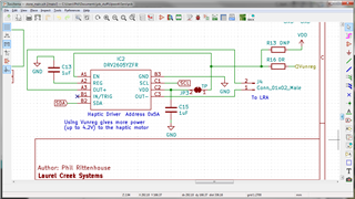
Here's an example of the configuration settings I am using 

// VG0832022D - 235Hz 1.4g 1.8Vrms
// https://www.vybronics.com/wp-content/uploads/datasheet-files/Vybronics-VG0832022D-Jinlong-G0832022D-datasheet.pdf
// SampleTime = 300use
writeRegister8(DRV2605_REG_RATEDV, 0x46); // Vrms
writeRegister8(DRV2605_REG_CLAMPV, 0x5B); // Vpeak
writeRegister8(DRV2605_REG_FEEDBACK, 0xB6);

writeRegister8(DRV2605_REG_CONTROL1, 0x93);
//writeRegister8(DRV2605_REG_CONTROL2, 0xF5); // Bidirectionl
writeRegister8(DRV2605_REG_CONTROL2, 0x75); // Unidirectionl
writeRegister8(DRV2605_REG_CONTROL3, 0x80);

writeRegister8(DRV2605_REG_MODE, 0x07);
writeRegister8(DRV2605_REG_CONTROL4, 0x20);

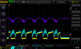
When I check the output on a 'scope I see both outputs in phase with each other.  At low RTPIN settings they just cancel each other out.  At higher settings one side starts a half-wave that drives the LRA but not at the expected frequency.  I see 470 Hz instead of the expected 235Hz

Any help would be greatly appreciated


  • Hi,

    Can you share your schematic? can you also check the connections of the LRA? is looks like there may be a poor connection on one of the terminals

    Regards,

    Arthur

  • Thanks Arthur,

    Here is the haptic section of the schematic. The Vunreg is coming from a 4.2V LiPo battery


    I checked by connections and they look solid.  I did notice though that if I attach the LRA to a mass (AA battery) the auto calibration starts to fail (status register doesn't have 0x08 bit set).

    Best regards,
    Phil

  • Hi Phil,

    In general for testing LRAs it is the best practice to mount the device to a mass, and sit it on a soft material, in our lab we use 100g aluminum bars ~the size of a phone, and rest them on some open cell foam. I mention this because LRAs can be unpredictable when left unmounted.

    So, when you have a mass on the LRA, do any other status bits get set?

    You should mount the LRA in a similar method as i mentioned above and run the auto calibration a few times to try and get it to pass

    Also, as a note. in the waveform you see the switching portion of the waveform, and the sort of smooth in phase portion. the switching portion is the actual driving voltage, and smooth in phase portion is the bias voltage of the front end ADC, trying to read the back emf. as you can see there is only one side of the LRA driver driving, this tends me to believe that it is not getting a valid BEMF voltage to measure.

    You should review 7.5.6 Auto Calibration Procedure in the data sheet and try to get calibration to pass, as you know this devices schematic is very simple, and if the LRA is connected correctly it should just be a bit of register settings to get it running.

    Regards,

    Arthur

  • I don't see Over Temp or Over Current set after calibration fails.  I can get the other status bits if you think they'd be helpful.  I will also try calibrating with a larger mass but in our application our device is very light. Do you have any guidance on what a minimum weight might be?

    For the Auto Calibration I found guidance for setting
      RATED_VOLTAGE[7:0]
      OD_CLAMP[7:0]
      DRIVE_TIME[3:0]
    Although, in this case Vibronics' datasheet does not specify an Overdrive voltage.  In that case, should I use the same value as the Rated Voltage?

    Finding the correct settings (if not the default) for the following seems to be a black art:
      FB_BRAKE_FACTOR[2:0]
      LOOP_GAIN[1:0]
      AUTO_CAL_TIME[1:0]
      SAMPLE_TIME[1:0]  
      BLANKING_TIME[1:0] 
      IDISS_TIME[1:0] 
    Do you have any guidance for knowing when the defaults need to be change for these?

    Thanks for all your help,
    Phil

  • Hi Phil,

    So a lot of these values do not have a formula associated with them, the designers just left these knobs available because for some actuators (edge cases that are large and high inductance, or small and very low inductance) they are needed

    the FB_BRAKE_FACTOR controls how aggressive the braking will be. in some cases the braking can be too strong and instead of bringing the LRA to a stop it will just cause it to go the opposite direction and oscillate. In this case you would want to lower this 

    I don't have any hands on experience with an issue related to LOOP_GAIN. but this parameter is setting the gain on the feedback path from the ADC in the front end. If this is set too high it can create instability in the driving waveform. in your case I would leave this as default.

    the AUTO_CAL_TIME just needs to be long enough for the LRA to reach a steady state vibration 

    I do not know exactly what SAMPLE_TIME does. I would just be quoting the D/S if I said anything here

    the BLANKING_TIME and IDISS_TIME are both time for the current and transients to dissipate in the actuator before the BEMF is measured. these should be set to about (atleast) 5 L/R time constants. We have seen cases where for large low resistance (~7 Ohm) LRAs the default values are not enough time for the current to dissipate, and the Auto cal and diagnostics will fail because the BEMF is saturating the front end ADC. However from the LRAs you mentioned I don't think this will be an issue.

    But i think that you should be OK with the default for all of these. 

    do you see any other status bits getting set?

    Regards,

    Arthur

  • Thanks for all the details Arthur.

    I sometimes see FB_STS bit set in the status.

    Can you clarify what the L/R time contant is (induction over reistance?)  I don't think the datasheet for my LRA includes the inductance.

    It looks like I might have found the issue when I switch the DRIVE TIME to 16 to match the 240Hz freq of my LRA 

  • Hi Philip, 

    Yes L/R is inductance/resistance. this is a helpful article explaining https://www.electronics-tutorials.ws/inductor/lr-circuits.html#:~:text=The%20time%20required%20for%20the,of%20the%20inductor%20in%20Henries

    Do you mean that you have resolved the issue?

    Regards,

    Arthur

  • It's a lot better now that I changed the DriveTime and dropped the gain but I still see hiccups on some parts (same make and model)

    Do the LRA manufacturers typically provide the induction or time constant values? I assume it's different than the vibration frequency?

    Do you think increasing the weight (our device is currently 22 grams) would help?

    Best regards,
    Phil

  • Hi Phil,

    you should use a mass that is reasonably close to what the end applicaiton will be. 22 grams is a bit light, but you just don't want the LRA to be loose and rattling around. if it is firmly mounted with the ability to vibrate some you should be fine.

    Can you share the waveforms in the current state again?

    some LRAs do give inductance but i didn't see that in the vibronics data sheets. the 5 L/R is a minimum value. going higher is OK. however the BLANKING_TIME and IDISS_TIME are time where the DRV is not driving the LRA. so as these times increase the vibration can get a bit weaker.

    if you want too test with higher BLANKING_TIME and IDISS_TIME I would also recommend you raise ZC_DET_TIME (zero crossing detect time)

    I am not the designer of this part so my knowledge on ZC_DET_TIME is limited, but from my past experience it seems that they may need to be raised together

    Regards,

    Arthur