This thread has been locked.

If you have a related question, please click the "Ask a related question" button in the top right corner. The newly created question will be automatically linked to this question.

DRV8313: How can I achieve synchronous operation?

Part Number: DRV8313

Hi Team.

I'm working on synchronous operation with drv8313, but motor doesn't work.

And I don't know the meaning of synchronous and asynchronous rectification exactly.

Should I supply 3-phase trapezoidal wave to INx while synchronous driving?

I don't understand why this chip is so difficult to operate.

Could you explain how I can operate it easily?

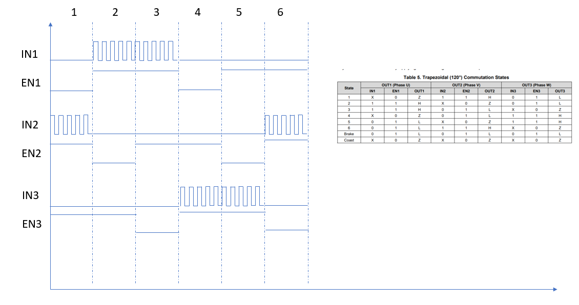
It doesn't work with Table 5. Trapezoidal (120°) Commutation States.

Thanks.

  • I also tried to supply PWM to INx with STM32F1.

  • Hi Robert,

    Synchronous rectification is achieved by applying INHx = PWM signal while INLx = 1. The outputs will switch synchronously depending on the state of INHx. Asynchronous rectification is not achievable on DRV8313 since the only valid states are synchronous OUTx outputs or Hi-Z OUTx outputs. 

    This post below better describes commutation states of DRV8313:

    e2e.ti.com/.../3973897

    Thanks,
    Aaron

  • Thank you Aaron.

    I tried to do as the chart above and motor worked.

    But motor doesn't work softly. 

    What else should I do for soft operation of motor?

    Thanks,

    Robert. 

  • Hi Robert,

    Please describe "soft" operation of the motor. Does the motor vibrate or make noise?

    The best way to make motor operation smooth is to match the Back-EMF of the motor with the current provided. The above commutation scheme uses 6-step sensored trapezoidal current. This will match the BEMF best of a trapezoidally wound motor, whereas sinusoidal current will best match the BEMF of a sinusoidally wound motor. 

    Does the motor operate smoother at lower voltages or duty cycles, or is it always vibrating? Can you take waveforms of OUT1, OUT2, and OUT3?

    Thanks,
    Aaron

  • Hello Aaron,

    I coded with your scheme above.

    The sensorless motor works but it has vibration too much.

    How can I reduce vibration?

    STM32F103 codes are as follows:

    int main(void)
    {


    HAL_TIM_PWM_Start(&htim2, TIM_CHANNEL_2);   //IN1
    HAL_TIM_PWM_Start(&htim3, TIM_CHANNEL_1);   //IN2
    HAL_TIM_PWM_Start(&htim3, TIM_CHANNEL_2);   //IN3

    while()

    {

    //1
    __HAL_TIM_SetCompare(&htim3, TIM_CHANNEL_1, 200);
    HAL_GPIO_WritePin(GPIOB, GPIO_PIN_13, GPIO_PIN_RESET); //EN1
    HAL_GPIO_WritePin(GPIOB, GPIO_PIN_14, GPIO_PIN_SET); //EN2
    HAL_GPIO_WritePin(GPIOB, GPIO_PIN_15, GPIO_PIN_SET); //EN3
    HAL_Delay(5);
    __HAL_TIM_SetCompare(&htim3, TIM_CHANNEL_1, 0);

    //2
    __HAL_TIM_SetCompare(&htim2, TIM_CHANNEL_2, 200);
    HAL_GPIO_WritePin(GPIOB, GPIO_PIN_13, GPIO_PIN_SET); //EN1
    HAL_GPIO_WritePin(GPIOB, GPIO_PIN_14, GPIO_PIN_RESET); //EN2
    HAL_GPIO_WritePin(GPIOB, GPIO_PIN_15, GPIO_PIN_SET); //EN3
    HAL_Delay(5);

    //3
    HAL_GPIO_WritePin(GPIOB, GPIO_PIN_13, GPIO_PIN_SET); //EN1
    HAL_GPIO_WritePin(GPIOB, GPIO_PIN_14, GPIO_PIN_SET); //EN2
    HAL_GPIO_WritePin(GPIOB, GPIO_PIN_15, GPIO_PIN_RESET); //EN3
    HAL_Delay(5);
    __HAL_TIM_SetCompare(&htim2, TIM_CHANNEL_2, 0);

    //4
    __HAL_TIM_SetCompare(&htim3, TIM_CHANNEL_2, 200); //IN3
    HAL_GPIO_WritePin(GPIOB, GPIO_PIN_13, GPIO_PIN_RESET); //EN1
    HAL_GPIO_WritePin(GPIOB, GPIO_PIN_14, GPIO_PIN_SET); //EN2
    HAL_GPIO_WritePin(GPIOB, GPIO_PIN_15, GPIO_PIN_SET); //EN3
    HAL_Delay(5);

    //5
    HAL_GPIO_WritePin(GPIOB, GPIO_PIN_13, GPIO_PIN_SET); //EN1
    HAL_GPIO_WritePin(GPIOB, GPIO_PIN_14, GPIO_PIN_RESET); //EN2
    HAL_GPIO_WritePin(GPIOB, GPIO_PIN_15, GPIO_PIN_SET); //EN3
    HAL_Delay(5);
    __HAL_TIM_SetCompare(&htim3, TIM_CHANNEL_2, 0);

    //6
    __HAL_TIM_SetCompare(&htim3, TIM_CHANNEL_1, 200);
    HAL_GPIO_WritePin(GPIOB, GPIO_PIN_13, GPIO_PIN_SET); //EN1
    HAL_GPIO_WritePin(GPIOB, GPIO_PIN_14, GPIO_PIN_SET); //EN2
    HAL_GPIO_WritePin(GPIOB, GPIO_PIN_15, GPIO_PIN_RESET); //EN3
    HAL_Delay(5);
    __HAL_TIM_SetCompare(&htim3, TIM_CHANNEL_1, 0);

    }

    }

  • The PWM frequency is about 24KHz.

    Thank you, 

    Robert

  • Hi Robert,

    I am not familiar with HAL structure of the STM32F103 codes. 


    Are your Hall sensor states correct? Please confirm by sharing waveforms of  motor phase outputs OUT1, OUT2, OUT3. Do they appear trapezoidal in shape?

    Thanks,
    Aaron

  • Thank you Aaron.

    Your kind answer resolved my problem succesfully.

    Regards,

    Robert.