A related question is a question created from another question. When the related question is created, it will be automatically linked to the original question.
If you have a related question, please click the "Ask a related question" button in the top right corner. The newly created question will be automatically linked to this question.
1. As long as you aren't trying to surpass a current of 4.7A, these inductors chosen should be fine. This post might also help with more information on this.
2. If you are setting the PWM signal to 0, the current would be driven to ground. Are you expecting a reverse current here?
3. They should not increase as mentioned so this should not be a problem. The supplies should be stable with the capacitor choices that are shown in the design.
4. The function of the LPF circuit is to transform the PWM signal into a sine wave which the input pin can take. As a reminder, this is an analog input.
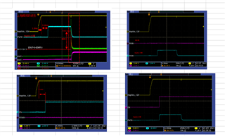
After the power is turned on, the IC itself will generate a 10ms PWM pulse. What is the reason for this?
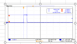
During the power-on process, a pulse will be generated when out+ rises from 0V to 6V. What is the reason for this pulse? How can this pulse be filtered out?
for Single end input, datasheet have following describe:
that means IN- have following three connect options or just have ① and ③ , what is different? ① IN-pull up to 3V; ② IN-tied to GND; ③ IN- 0.1uF to GND
The LPF loop needs to be added to the PWM control loop. What is its function? Are the settings on our circuit reasonable? In the circuit design of our company, if the capacitor of PWM+ is removed, it is easy to pull down INTZ and cause the drive IC to not operate. Please also help to identify the reason.