This thread has been locked.

If you have a related question, please click the "Ask a related question" button in the top right corner. The newly created question will be automatically linked to this question.

MCT8316Z: Problem in reading SPI config registers

Part Number: MCT8316Z

Hello,

We have develop a pcb for MCT8316ZR SPI version in that PCB I am able to read Registers but I am not sure all values are correct because some registers have default value and some have different. And when I have written 0x03 to register address 0x03 to unlock all registers. And I verified it by reading it back it was showing value 0x03 only. But when I read address 0x04 it was showing 0x40 instead 0x80 (default value). And When I have written 0x86 to this register and read it back then it returned 0x82. 

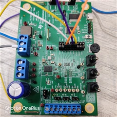
So, I thought to try it out on development board (MCT8316ZT dev board) first. So, I replaced the MCT8316ZT with MCT8316ZR but I am not able to read anything and even Buck output led is not even turned on when I powered it up. 

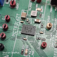
I am attaching the pic development board please check it that if I am making some mistake in changing resistors for Hardware control to SPI control. and I am also attaching the pic of Chip. Please check it that is it correct chip or not?

Regards

Imran

  • Hi Imran,

    If the buck output LED (VBK) is not lit up when powering the board, it is still in sleep mode (nSLEEP = 0). The onboard MSP430 pulls this signal high, so can you plug in the Micro-USB at the bottom to power the MCU to provide nSLEEP = 1? Once powered on, then you can use your external MCU to communicate with the MCT8316Z0R using SPI. 

    Thanks,
    Aaron

  • Hi Aaron,

    Thanks for quick reply.

    I have already connected Micro-USB to the board and even I cross verified that at nSleep we are getting 3.3 v. 

    Regards

    Imran

  • Hi Imran,

    In order to further debug why the Vbk led is not on despite nSleep being 3.3V, would you be able to provide the following measurements:

    1. measure the AVDD pin voltage to ensure that it is outputting around 3.3V. 

    2. Measure the Vbk voltage to see if there is any voltage on that node

    3. Measure the sw_buck to see if the buck switch node is outputting any voltage.

    Regards,

    Anthony 

  • Hi Anthony,

    1. AVDD = floating 170 mV

    2. Vbk = 0.3 mV

    3. sw_buck = 0.3 mV

    In our developed PCB we are able to communicate via SPI but it is Showing Buck fault but we are not using internal buck. So, I disabled Buck from SPI. 

    And tried to run motor then it is showing Motor lock error.

    Please provide your email ID. So, that we can send you our schematic for better clarity.

    Regards

  • Hi Imran,

    I will private message you and I can take a look at the schematic offline. 

    Regarding the issues you are experiencing in evaluating the MCT8316ZR on the EVM, since both AVDD and Vbk are powered by VM, and AVDD and Vbk are not powering on, this seems to indicate that the VM supply is not connected to the device. Could you probe VM to see if it is properly powered? I would recommend probing VM on the VM side of C4 to see if power is being supplied to the MCT8316. If this is not the case, then you will want to check your power supply that you connected either to the VBAT connector or the VM connector to power the device. If you are measuring a sufficient VM voltage on the C4 capacitor to power the device then I would double check the solder connections connecting the VM pins of the MCT8316ZR to the VM pads on the PCB. Regards,

    Anthony Lodi

  • Hi Imran,

    Since we discussed your schematic offline I will go ahead and close this thread. If you have further questions, feel free to click on "Ask a related question".

    Regards,

    Anthony Lodi