This thread has been locked.

If you have a related question, please click the "Ask a related question" button in the top right corner. The newly created question will be automatically linked to this question.

DRV110EVM: When DC24V is input, it does not change to hold current.

Part Number: DRV110EVM
Other Parts Discussed in Thread: DRV110

Dear Specialists,

My customer is evaluating DRV110EVM and has a question.

I would be grateful if you could advise.

---

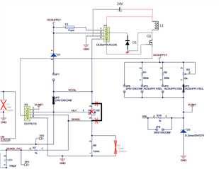
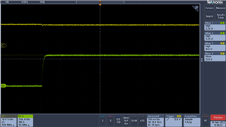
When DC24V is input, it does not transition to hold current.
Up to 18V, the peak current changes to the hold current.

Could you please see attached waveform

Image of Vin voltage ① and current waveform ④ when DC24V is applied (DC24Vin.png) and DC18V is applied (DC18Vin.png)

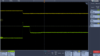
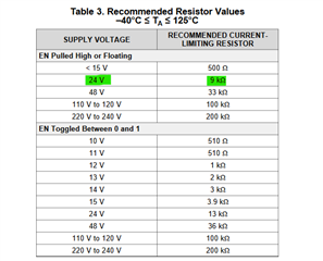
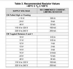
JP3 is short-circuited by applying DC24V from DCSUPPLY.
R3 = 9kΩ, ROSC = 200kΩ, RHOLD = 100kΩ, RPEAK = 150kΩ are set.
No other changes have been made.

Could you please let us know what could be the cause 
Is the device broken?

---

I appreciate your great help in advance.

Best regards,

Shinichi  

  • Hi shinichi,

    Let me look into this and I will get back to you within 24 hours.

  • Hi Pablo,

    Thank you for your reply.

    I'm looking forward to waiting your advise.

    I appreciate your great help.

    Best regards,

    Shinichi

  • Hi Shinichi,

    Can you provide an overview of the hardware set-up. What jumpers were populated and detailed test procedure. I can go to the lab and debug it with one of our EVMs.

  • Hi Pablo,

    Thank you for your reply. I'm sorry for late reply.

    I'm confirming the EVM's setting with the customer.

    I'll feedback when I obtain.

    I appreciate your great help and cooperation.

    Best regards,

    Shinichi

  • Shinishi,

    No worries. Let me know when you hear back from the client.

  • Hi Pablo,

    Thank you for your reply.

    I could obtain the information about DRV110EVM setting.

    Could you please see below.

    ---

    (1)About JP1 to JP9 settings→ Short JP2 and JP3. Others are open.

    (2) DC SUPPLY is connected to pin P1-2. (To apply power without passing through a fuse)

    (3)R3(9kohm), ROSC(200kohm), RHOLD(100kohm), RPEAK(150kohm) are the values adjusted for variable resistance.

    (4) EN is operated by applying DC3V directly from the power supply.

    (5)DC24V is supplied and EN is turning on / off.

    (6)about the load connection

    → Q2 and D1 are not used, the power transistor (R6020) and diode (RF2001) are connected externally, and the load is connected to the coil.

    Could you please see attached connection image.

    DRV110EVM connection .xlsx

    Is there any mistake in setting?

    Could you please provide the waveform EN is ON. (DC24V 18V)

    ---

    I appreciate your great help and cooperation.

    Best regards,

    Shinichi

  • Hi Shinichi,

    → Q2 and D1 are not used, the power transistor (R6020) and diode (RF2001) are connected externally, and the load is connected to the coil.

    Could you please see attached connection image.

    I think this is where the problem is coming from. Below is a schematic drawing on how to properly connect the external diode and FET along with the power supply. Note that JP7 is shorted and Q2 is removed from the PCB and pin 2-3 are shorted.

    One more thing I recommend is not trying EN pin to external supply. Just leave the EN pin floating (unconnected). There is an internal pull-up resistor on EN which will enable the device when EN is open. This is a more reliable way to enable the device than pulling EN high.

    Also, What is the value of VIN? Is it equal to 24V? If Vin is higher than 14V, a limiting resistor on the VIN line will be required as specified in the datasheet (see below for recommended resistor values). If VIN=24V, R10 on the EVM should be replaced with 9kΩ. If VIN current is not limited properly, it can cause damage to the IC and even cause current regulation issues.

  • Hi Pablo,

    Thank you for your reply.

    I'll share your suggestion with the customer.

    When the customer has an additional question, I consult you again.

    I appreciate your great help and cooperation.

    Best regards,

    Shinichi

  • Hi Pablo,

    The customer has a question about your suggestion.

    Could you please confirm and advise.

    ---

    (1) If pin 2-3 of Q2 is short-circuited, OUT and SENSE will be short-circuited.

    A short circuit occurs between G and S of the transistor.

    I think it should be only removed Q1.

    (2) The connection destination on the anode side of D1 should be Drain of Q1.

    In other words, D1 is parallel to L1.

    Could you please see below.

    (3) Vin is normally 24V, experimentally 15V.

    So R10 should be 9kom when Vin is 24V and 500ohm when Vin is 15V.

    Could you please confirm if the customer's phenomenon can be reproduced under these conditions.

    ---

    I appreciate your great help and cooperation.

    Best regards,

    Shinichi

  • Hi Shinishi,

    ) If pin 2-3 of Q2 is short-circuited, OUT and SENSE will be short-circuited.

    A short circuit occurs between G and S of the transistor.

    Thanks for catching this mistake, I failed to see this short. So just remove the FET.

    The connection destination on the anode side of D1 should be Drain of Q1.

    In other words, D1 is parallel to L1.

    Yes. That is correct.

    Vin is normally 24V, experimentally 15V.

    So R10 should be 9kom when Vin is 24V and 500ohm when Vin is 15V.

    Could you please confirm if the customer's phenomenon can be reproduced under these conditions.

    ---

    After implementing the set-up with the corrections, they should be able to get proper functionality.

  • Hi Pablo,

    The customer confirmed right setting you mentioned above, but the device didn't start up.

    Does this means the device was damaged.

    To clarify if the device is broken, could you confirm the operation of DRV110EVM under the same conditions?

    I appreciate your great help and cooperation.

    Best regards,

    Shinichi

  • Hi Shinichi,

    I will have to go to the lab to run the test. I am very busy with other work at the moment so please give me about 2 to three days to obtain the information.

  • Hi Pablo,

    Thank you for your reply.

    It would be very helpful you could check the operation of EVM.

    The EVM works properly in the application circuit, the customer will understand if the device is damaged.

    I'm looking forward to waiting your reply.

    I appreciate your great help and cooperation.

    Best regards,

    Shinichi

  • Hi Shinichi,

    It seems like the device or something on the EVM is damaged. I used a new EVM in the lab today and followed your instructions (except that I used board diode and FET). I noticed that when R3 is brought down to 0Ω, the supply current suddenly jumped to around 1-A. When using VIN>14V, the VIN current should be limited in order to prevent damage to the IC. The EVM was working perfectly fine before. I think if the customer set R3 to 0Ω when adjusting the potentiometer, this caused some damage. 

    My recommendation is to get a new EVM and adjust the potentiometer before turning on power. You can also limit the power supply current.

  • Hi Pablo,

    Thank you for your reply and checking the EVM. 

    I'm sorry for late reply.

    I understand the new EVM damaged 

    When R3 is 0ohm, output current suddenly flowed to 1A 

    (1) Please let me check.

    What was the value of R10 at that time,1kΩ or 10kΩ.

    If it is 1kΩ, overcurrent may have flowed.

    (2) The customer changed to the new device in the EVM, but the circuit did not work properly.

    Is it possible to comment which part is broken.

    (3) I'll share R3(potentiometer) never be 0ohm and current limit of power supply is needed.

    Also total value of R3 + R10 set appropriately. When 24V, R3+R10 is 9kohm. 

    I appreciate your great help and cooperation.

    Best regards,

    Shinichi

  • Hi Shinichi,

    Thank you for the information.

    (2) The customer changed to the new device in the EVM, but the circuit did not work properly.

    Is it possible to comment which part is broken.

    So the customer replaced the IC on the EVM with a good one and the problem still occurs?

    (3) I'll share R3(potentiometer) never be 0ohm and current limit of power supply is needed.

    Also total value of R3 + R10 set appropriately. When 24V, R3+R10 is 9kohm.

    So they set current limit on their power supply? This can help but could be possible that it was not limited to a low enough current to prevent damage.

  • Hi Pablo,

    Thank you for your reply.

    (2) Pablo said :

    So the customer replaced the IC on the EVM with a good one and the problem still occurs?

    >Yes, the customer replaced good DRV110 on the EVM, but the problem still occurs.

    So, the other components may be damaged. 

    This is the reason I consult you. Which part is broken?

    Pablo said:

    So they set current limit on their power supply? This can help but could be possible that it was not limited to a low enough current to prevent damage.

    >I don't know if the current limit on the power supply side has been set so far.

    I'll ask them to set the current limit the next time they check.

    I'll feedback when I obtain the customer's additional information. 

    I appreciate your great help and cooperation.

    Best regards,

    Shinichi

  • Hi Shinichi,

    Thanks for the confirmation and please let me know when you hear back from customer.