


Hi team,
Here's some issues may need your help:
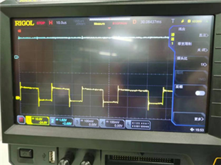
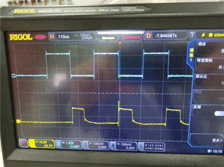
1) Regarding the drive waveform of 8256E, the description in spec is "The EN input drives the waveform PWM, and the PH pin inputs the direction signal so that out1 and out2 output the corresponding waveform".
The following two figures correspond to 100% and 50% of the EN pin input (blue input and yellow output), and the output waveforms are 50% and 25%, respectively, which is different from what the spec shows:
2. When the motor is hooked up, it sees no load, so the resistive process is removed, that is, the chip can still input the PWM waveform without output, and it is found that the load is still not hooked (no output from the chip). But the MCU side is still feeding the chip input waveform (possibly chip protection), after a while the chip is burned out.
When the chip is already protected, will it still burn out if it is still being fed into the signal?
Tested with no load after removing the resistive process, no problem, and theoretically, load of the motor with a full load of around 3 A does not trigger protection (that is, the drive chip appears to be auto-protected, but normally it is not protected in this case. If the load is halved, it can operate normally, but at a slower speed, it appears as full load).
Could you help check this case? Thanks.
Best Regards,
Cherry

