This thread has been locked.

If you have a related question, please click the "Ask a related question" button in the top right corner. The newly created question will be automatically linked to this question.

DRV8305-Q1: 500mA current spikes on PVDD pin

Part Number: DRV8305-Q1

Hello,

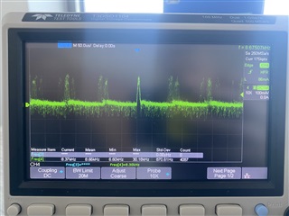
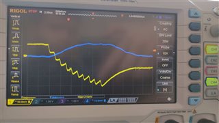
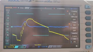
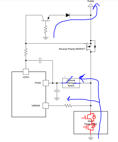
I have noticed 500mA or so current spikes on PVDD pin apart from normal 35mA power consumption. This has been measured while no PWM signal was applied to the driver and the gates were enabled. After disabling gates, no spikes are visible. At first, I connected it to gate charge pumps, but the frequency of them is far too low (8.3kHz) unless charge pump works in hiccup mode even when no transistors are driven. Could you tell me, if this is a bad measurement method, something is wrong with my design, or if it is a normal operation?


  • Hi Mateusz,

    This is pretty noisy. The 8.3kHz seems pretty low if this is not PWM frequency. There also appears to be very high frequency lower amplitude noise as well between the 8.3kHz pulses. Is there inductance between the supply and system, i.e. long wires?

    Are you using a clean power supply or battery? When EN_GATE is low, VCP_LSD and the tripler charge pump is disabled. Can you check if this noise is also apparent at the VCPH and VCP_LSP pins? The required bypass caps should be placed close to the driver IC, or else long current loops and added inductance can cause noise at these pins. Also please ensure that the device is soldered correctly and PVDD bypass caps are placed close to the IC as well.

    For measurement, also ensure you are measuring as close to the driver IC pins?

    Thanks,
    Aaron

  • Hi Aaron,

    PWM frequency is much higher, the test was performed with a better setup ie. shorter leads and lower value shunt resistor, and the high frequency spikes disappeared, while the big ones stayed. We are using linear lab power supply. All bypass capacitors are within 7mm of IC and everything has solid copper plane underneath. Voltage on VCP_LSP is solid 12V, and VCPH is 24V. I didn't yet measure currents on these pins, but it must be something connected to the driver because once we disable gates, spikes go away. As for soldering, we have three identical test boards and they all show the same behavior. I doubt we could go wrong with soldering three times. We'll be probing more in the meantime, if anything changes we'll let you know, but as of now - we're pretty much out of ideas.

  • Hi Mateusz,

    Thank you for your points and checking with shorter leads. 

    I looked on E2E and see this person had the same issue when EN_GATE was low, as there were possible concerns with DVDD/AVDD regulators causing noise due to capacitor placement. https://e2e.ti.com/support/motor-drivers-group/motor-drivers/f/motor-drivers-forum/1004877/drv8305-q1-emi

    Can you check these circuits to see if you see any coupling? Also ensure that the current loops are minimized for all bypass capacitors to reduce inductance in the regulators. Caps should have a voltage rating 1.5x to 2x the DC bias voltage for full effective capacitance. 

    Can you share schematic and/or layout? Feel free to send me a direct message if you do not wish to share over the forum. 

    Thanks,
    Aaron

  • Hi Mateusz,

    Can you also check CP1H, CP1L, CP2H, CP2L, VCPH, and VCP_LSD with respect to GND to see if there is also any 8.3kHz noise similar to PVDD? It is possible that the charge pump controller is operating very slowly and coupling into PVDD because a small IDRIVE setting is used. When EN_GATE goes low, the charge pump is disabled so this would remove the noise. 

    Thanks,
    Aaron

  • Hi Aaron,

    It turns out, that charge pump is periodically switching on and off with this frequency. On the attached shots blue is current and yellow is voltage (first photo is supply, second VCPH). I guess there is nothing we can do about it apart from LC filter... 

  • Hi Mateus,

    Does the frequency reduce in amplitude when a higher IDRIVE setting is used? 

    Can you filter out the noise using a common mode choke, more supply bulk capacitance, or PVDD bypass caps?

    Thanks,
    Aaron

  • We could not tackle this problem with any register settings. All in all, we can live with that - just better to know where it comes from. Could I ask you about another thing in this thread? We do not know why you suggest 100 ohm resistor connected to VDRAIN. In datasheet, it says it protects this pin from reverse polarity, but in figure 14 (SLVSD12D) it is used in conjunction with rev. pol. MOSFET. What is the use of it, if the supply line in this schematic is already protected?

  • Hi Mateusz,

    The 100-ohm resistor is used to limit current into the VDRAIN pin when voltage transients occur from PVDD.

    Thanks,
    Aaron

  • Hi Aaron,

    And when could such transient occur? Is it only when motor is freewheeling, and the supply is turned off?

  • Hi Mateusz,

    Yes, that is one scenario. Or even during motor current switching if there's inductance in the path, or motor operation that requires large change in current such as starting or braking. Supply bulk and bypass capacitance can help with mitigating transients, but the VDRAIN resistor can help limit current into the pin. 

    Thanks,
    Aaron

  • But if I don't protect PVDD pin from reverse polarity (where "Optional Filtering or Switch" block is), the IC will be dead anyway, right? They have the same voltage absolute maximum values from what I see.

  • You can use the "optional switch" configuration to protect PVDD in the case of a reverse polarity condition (blue current path). VDRAIN has no dependencies in the IC, so it should be okay with a series limiting resistor. PVDD will not be powered with negative voltage in this scenario while the reverse polarity kicks in to oscillate the voltage back to 0V. 

    Thanks,
    Aaron