This thread has been locked.

If you have a related question, please click the "Ask a related question" button in the top right corner. The newly created question will be automatically linked to this question.

DRV8301: Could not get the accurate current value from the sampling resistor

Part Number: DRV8301

Hi Team,

The customer is using DRV8301 and found out that they could not get the accurate current value from the sampling resistor. They tried to connect an external galvanometer to provide an accurate current to the sampling resistor but they found that the values they got were very different. At 500mA, it was almost accurate, but when the current was increased to 1A, their master calculated a current of 1.3a, and as the current increased, the measurement deviation increased.

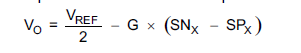
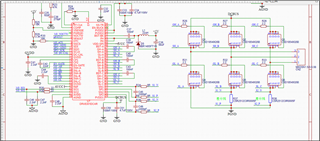
The customer would like to know if there is any calibration mechanism for DRV8301? The magnification they currently use is 80 times and the sampling resistance is 0.5 milliohms. The schematic diagram of the customer circuit is shown below.

Would you kindly help to analyze it and give some suggestions? Thank you very much!

Regards,

Marvin

  • Hi Marvin,

    You can calibrate the DRV8301 CSAs by:

    • Pulling the DC_CAL pin high (calibrates both CSAs)
    • Setting the DC_CAL_CH1/2 bits in SPI to calibrate each CSA

    Calibration helps with correcting offset drift error over temperature. Is the incorrect measurements at room temperature or across temperature?

    If it's across temperature, device calibration will help removes those errors in measurement due to offset drift. 

    If it's at room temperature, make sure the customer is sampling the SO1 and SO2 output voltages after the CSA settling time. Sampling the ADCs when the CSAs have not settled yet can result in an error in current measurement. 

    Thanks,
    Aaron 

  • Hi Aaron,

    The customer have a question about the CSA settling time, if they calibrate the DRV8301 CSAs by Pulling the DC_CAL pin high (calibrates both CSAs), then they pull the DC_CAL pin low and Sampling the ADCs. How long is ok between pulling the DC_CAL pin and Sampling the ADCs?
    I hope you can help.
    Regards,
    Marvin
  • Hi Marvin,

    Great question, I don't immediately have that information right now, but I will reach out to others on the team to see what I can find on this issue. I will try to get back to you on this Monday or Tuesday.

    Regards,

    Anthony Lodi

  • Hi Anthony,

    Thank you for helping. Please let me know if you have information about this.

    Regards,

    Marvin

  • Hi Marvin,

    I haven't been able to find the information that I need, I reached out to 2 team members today to see if I can get this information, I hope to hear back from them tomorrow or Wednesday. Will keep you updated.

    Regards,

    Anthony Lodi

  • Hi Marvin, 

    If I can't find any information on this by tomorrow, I intend to run a test in lab tomorrow to get an approximation of this data.

    Regards,

    Anthony Lodi

  • Hi Anthony,

    Thank you. Please let me know if you are done with the test. 

    Regards,

    Marvin

  • Hi Marvin,

    Based on my current schedule for today I intend to run this test this evening, will try to have the data to you by tomorrow at the latest.

    Regards,

    Anthony Lodi

  • Hi Marvin, 

    I ran into some issues with the test setup so I was unable to gather the data. I will discuss next steps on this sometime Wednesday.

    Regards,

    Anthony Lodi

  • Hi Anthony,

    Thank you. I will wait until then.

    Regards,

    Marvin

  • Hi Marvin,

    I think I figured out the issue with my test setup, I will update you tomorrow. I will work on the data tonight and tomorrow and try to provide it by tomorrow end of day.

    Regards,

    Anthony Lodi

  • Hi Marvin,

    I was able to get the data today, it looks like from the time DC_CAL is pulled high to the time that the amplifier inputs are shorted and the output is stable is less than 10us, and the time from DC_CAL being pulled back low to the time that the inputs are no longer shorted and the CSA outputs are settled is less than 10us. So waiting 10us should be sufficient to allow the outputs to stabilize. I will provide data and a more detailed explanation hopefully Monday.

    Regards,

    Anthony Lodi

  • Hi Anthony,

    Thank you for the follow-up.

    I will wait for the data and for the detailed explanation as you mentioned.

    Regards,

    Marvin

  • Hi Marvin,

    Thanks for your patience in waiting for my response! I have attached the test results here. Note that this is just a bench test that I performed on 1 unit on 1 current sense amplifier (CSA). This is not a guarantee of how it will perform but is rather a starting point for the customer to understand what is going on when the DC_CAL pin is used to short the inputs of the CSAs.

    The purpose of the DC_CAL pin is to short the CSA inputs to allow the user to then measure the SOx outputs to determine what the offset of the amplifiers are when the inputs are shorted. The microcontroller will need to read these SOx values and use the values measured in place of the VREF/2 value in the current calculation equation shown below. Since there is some offset in the CSAs, the output of the CSAs with the inputs shorted are not going to be exactly VREF/2, there will likely be some offset voltage to consider, which the equation below doesn't take into account. That is why you would want to replace the VREF/2 value with the value measured at the output of the CSA when the inputs were shorted. 

    One thing to note in the datasheet is that the gain isn't necessarily exactly 80V/V for a gain setting of 80. The min gain is 75 V/V and the max gain is 85V/V for a gain setting of 80, with the average gain at 25C being 80 V/V. 

    Regards,

    Anthony Lodi

    Marvin DRV8301.pdf