This thread has been locked.

If you have a related question, please click the "Ask a related question" button in the top right corner. The newly created question will be automatically linked to this question.

DRV8874: Current chopping turn-off much slower than tDEG spec

Part Number: DRV8874
Other Parts Discussed in Thread: DRV8871

Hi,

the DRV8874 datasheet specifies tDEG current regulation deglitch time as 0,6us, but I observe that the bridge trips 5us after Itrip at high dI/dT.

IPROPI follows the measured current perfectly, so this seems to be an internal delay.

Setup: Vref=3.3V, R-IPROPI=2k4, IMODE = GND, VM=12V, static IN1=H, IN2=L, load inductance 1mH or 66uH.

The scope screenshot shows the output current (blue), V-IPROPI (pink) with 66uH load and output current with 1mH load (reference/white).

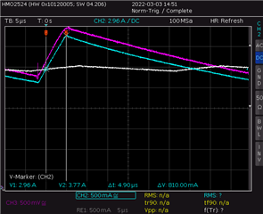
As you see, the DRV8874 trips at approx. 3A with slow dI/dT, but it trips at 3.77A at dI/dT=0.165A/us, or 5us after passing the 3A mark.

What's going on?

  • Hi Oliver,

    Thank you for posting your question to the forum.

    Please give me 24 hours to research and I will get back with an answer soon.

  • Hi Oliver,

    Based on your ipropi resistor and VREF voltage, the itrip current limit should be 3.66A [(3.3/2000)/0.000450].

    Can you re measure the tDEG? It should be closer to the specified 0.6µs.

  • Hi Pablo,

    thanks for your reply.

    "2k4" is a common notation for 2400 Ohms, so the nominal trip point is 3.3V/(2400V/A*450µ)=3.06A.

    As you see in the white trace captured with slow dI/dT (L=1mH), it exactly trips at the calculated current.

    Besides, the pink trace V(IPROPI) goes way over 3.3V at high dI/dT but trips at 3.3V with low dI/dT.

  • Oliver,

    Understood. I misread the resistor notation.

    Let me have some more time to look into this.

  • Hi Oliver,

    I think I have a good idea what's happening.

    When the current rises very quickly, the current can be higher than the regulation limit due to internal delays. You are running in a corner case with the very low inductance.

    Is this delay a big concern for your application?

  • due to internal delays

    that's my guess from the original posting.

    Is this delay a big concern for your application?

    The documentation not stating this is indeed a big issue.

    As I wrote in the original posting: "the DRV8874 datasheet specifies tDEG current regulation deglitch time as 0,6us, but I observe that the bridge trips 5us after Itrip at high dI/dT."

    That's nearly ten times the specified delay. Please explain if I misinterpreted the DS and tell me where the observed behavior is documented.

  • Hello Oliver,

    Pablo is out of office today. Please allow some time for further support. Thanks!

  • Hi Oliver,

    Apologies for late reply. Was out of the office Friday and was unable to reply the last two days.

    Let me explain the specification on the DS. The deglitch time in the DS is taken from characterization data taken with various ICs to observe IC to IC variation. The Typical value in the datasheet is, as the name implies, the typical value measured during characterization and specific test conditions. Of course there can be corner case that can cause this value to vary greatly. However, those corner case are not common.

    What I recommend doing to verify is using a purely resistive loadand set the current limit below the max output current (V/R). Measure the deglitch time. If it is still showing as 5us, it could mean something else could be causing the large deglitch time.

  • What I recommend doing to verify is using a purely resistive loadand set the current limit below the max output current (V/R). Measure the deglitch time.

    Issues with this suggestion:

    1. tDEG is a dynamic parameter applicable to the current regulation operation while IN1/IN2 are static. How could this be measured with a static ("purely resistive") load?

    2. What insight do you expect to gain from this experiment?

    Even if I used steerable current sinks, I don't see what these could do better than an inductor.

    Please keep in mind that we are investigating the current regulation mode of the DRV8874, therefore the current has to be sustained if the bridge changes to "both low-side  FETs on", and switching to back L-H should happen with current flowing in both low-side FETs. Otherwise (with your suggestions) we had high dV/dT at the IPROPI output.

    If you are sure that your suggestion has a benefit, please explain how to conduct this test and what you expect.

    there can be corner case that can cause this value to vary greatly

    A factor of eight (5us:0,6us) is more than a corner case in my opinion.

    Either I'm overlooking another characteristic of the DRV8874 (please tell me), or there is a documentation issue (at least).

  • Hi Oliver,

    Please disregard my suggestion of using resistive load. I understand now this will not provide meaningful results.

    Let me investigate this a little more. i will run some experiments tomorrow to try to understand this anomaly. I will also reach out to our team internally to understand why you are measuring higher than expected deglitch times

  • In the mean, I made also measurements with 350uH,and I tested different samples.

    The 350uH measurements (dI/dT = 40mA/us at 12V) confirm the "constant delay" assumption: With Vref=3.3V, the bridge trips 4.6us after IPROPI  rises above 3.3V.

    I tested also my first prototyping samples, and these have a shorter delay of only 1.6us.

    This made me realize a mistake on my part: The samples with the long delay are DRV8874-Q1. My apologies that I reported the wrong part number and therefore wrong tDEG spec in my initial report! The chips with the short delay are "non Q" DRV8871.

    But the much slower Q1 devices don't explain the measured values completely: Q1's tDEG spec is 1.7us. The measured 4.6us is "only" 2.7 times the spec, not eight to ten times as I reported initially. Still worth to investigate.

  • Any news about tDEG measured 4.6us vs. 1.7us spec?

  • Hi Oliver,

    Sorry for late reply. Unfortunately, I have not been able to find the answer to your question. I will need more time

  • Hi Oliver,

    Sorry for late reply. I have an update.

    TDeg time is only for the ITRIP comparator. After that Driver takes more time to turn and enter Decay where current starts to fall. So the tDEG shown in the datasheet figure only shows the ITRIP comparator time and does not include the extra delay for the driver to enter into decay mode.

    Regards,

    Pablo Armet

  • Hi Pablo,

    what purpose would it serve to specify an internal parameter that no one can measure or observe, and that would be of no use to any developer?

    Regardless, Figure 6-1 does not support your hypothesis: tDEG is indicated from IPROPI crossing Vref to IPROPI peak. And that's exactly what I measured and presented with the scope screenshot in the original posting.

    Well, Figure 6-1 IPROPI trace doesn't take into account tFALL, but even if tFALL (let's say 1/2 tFALL - the mid of the edge) is taken into account: tFALL is only 500ns in the Q1, so tDEG + 1/2 tFALL is still less than 2us.

     Oliver

  • Oliver,

    Let me look into this a little further and I will provide a response within 24 hours. Apologies and thanks in advance for your patience.

  • Hi Oliver,

    Apologies for long delay.

    The diagram in the datasheet does not show the extra time required for the driver to go into decay mode. And that is where the extra time is coming from.

  • The diagram in the datasheet does not show the extra time required for the driver to go into decay mode.

    Then the diagram is wrong, isn't it?

  • Hi Oliver,

    Yes. The labeling should include the extra delay. We will work to fix it in the next datasheet revision.

    Regards,

    Pablo

  • glad I could contribute to improve the docs. I hope you forgive my persistence.

    Best regards

    Oliver