This thread has been locked.

If you have a related question, please click the "Ask a related question" button in the top right corner. The newly created question will be automatically linked to this question.

DRV8343-Q1: VM Blackout Behavior

Part Number: DRV8343-Q1

Hello,

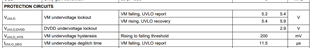
When VVM drops below its Min operating range 5.5 V in a system shutdown sequence, for example, and then it rises again on the way (3.3 V, for example) before reaching 0 V, will the DRV8343S-Q1 always successfully restart? Or, can it fail? How will the DRV8343S-Q1 behave?

In this case, 5.5 V is always applied to the ENABLE pin regardless of the VVM voltage.

Best regards,
Shinichi Yokota

  • HI Yokota-san,

    this behavior is captured by our undervoltage circuit/protection feature specifically on our VUVLO spec in our datasheet here: https://www.ti.com/document-viewer/DRV8343-Q1/datasheet/electrical-characteristics-x8427#x8427 

    Specifically, the system shutdown sequence happens when VM drops below VM falling VUVLO spec, and restart begins when VM increases above the VM rising VUVLO spec highlighted in the table below. Note that there is a 200mV (typ) hysteresis, as well as deglitch time associated with this protection circuit. 

    With that in mind, in the the scenario you described, if VM drops below  VM falling VUVLO spec (3.3V is sufficiently below), and then recovers above VM rising VUVLO spec max (5.9V for this device), and this transition takes longer than deglitch time spec, device is expected to restart.  

    Hope that helps!

    ~Dung

  • Dung-san,

    I'd like to ask one more question.

    I'm concerned if the DRV8343-Q1 always successfully shuts down as the VVM goes down and it always successfully restarts again as the VVM goes up when the DVDD regulator output is applied to the ENABLE pin to keep the ENABLE pin High.

    Is it OK to tie the DVDD pin to the ENABLE pin to keep the ENABLE pin High in real applications?

    Best regards,
    Shinichi Yokota

  • Hi Shinichi-san,

    Dung will answer your question tomorrow.

    Thanks,
    Aaron

  • Hi Yokota-san,

    if the customer does not need to ever put the device into sleep mode, it is OK to tie ENABLE pin high. They can certainly do that by leveraging the DVDD regulator output (3.3V is considered high logic). However, to limit current draw to this pin, you can add a pull-up resistor to the design.

    ~Dung

  • Dung-san,

    I'd like to ask one additional question. What kind of situation does this description assume? If it's a sink current into the ENABLE pin by its internal pull-down resistor of about 60 kΩ, I don't think it would have an impact on the DRV8343S-Q1 operation since it's only about 55 µA (≈ 3.3 V / 60 kΩ). Besides, which voltage do you assume the pull-up resistor is tied up to?

    However, to limit current draw to this pin, you can add a pull-up resistor to the design.

    Best regards,
    Shinichi Yokota

  • Hi Yokota-san,

    you are correct, ENABLE pin does have an internal pull-down and should effectively limit current draw per your calculation. In this case additional pull-up is not necessary. That guidance is typically mentioned as best practice when connecting pins directly to supply when you might not know how the pins are internally configured. 

    ~Dung