This thread has been locked.

If you have a related question, please click the "Ask a related question" button in the top right corner. The newly created question will be automatically linked to this question.

DRV8884: External Pull Up / Pull Down resistor value selection

Part Number: DRV8884
Other Parts Discussed in Thread: DRV8886

Dear Sir,

I have fixed mode of operation of IOs of DRV8884 like TRQ, M1/M0, DECAY.

Details are as below.

1)  TRQ, M1 - need to be logic low.

2) M0 - need to be logic high.

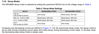
3) DECAY - 2.9 (slow decay for both increase/decrease steps)

Query is as below:

as per datasheet, M0 & TRQ pin is TRI-LEVEL Input pins; DECAY is QUAD-LEVEL input pin; M1 is LOGIC-LEVEL input.

Can I connect TRQ, M1 pins directly to ground OR I have to use some kind of external pull down resistor to make them logic low.

Can I connect M0,DECAY pins directly to DVDD pin of DRV8884 IC OR I should use some external series resistor while connecting to DVDD pin OR I should use external logic supply voltage instead of DVDD pin.

Regards,

Jigar

  • Hello Jigar,

    Thanks for checking with our team. To answer your questions:

    1. Connecting M0 and TRQ to GND is fine, there is an internal pulldown resistor typically 32k. Adding external pulldown resistor can mess with the input logic low voltage (VIL) and cause it to not trigger. 
    2. Connecting M1 directly to DVDD is fine due to internal pullup resistor. Same reasoning as above but with VIH.
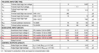
    3. Connecting DECAY directly to DVDD should be fine. Please be sure to connect a 135k resistor to GND to set the DECAY mode.

    Best regards,
    Tilden

    EDIT: Updated to correct reasoning.

  • Hi Tilden Chen,

    Thanks for your Guidance.

    I will go through your suggestion.

    I asked this question because I doubt that whether these pins might be damaged or not due to connecting directly to ground or DVDD.

    Regards,

    Jigar

  • Hello Jigar,

    I updated my answer since some of the reasoning was previously incorrect. Please also remember on the DECAY pin to connect a 135k resistor to GND for slow decay on both increasing and decreasing steps.


    Best regards,
    Tilden

  • Hi Tilden,

    Below I have found in datasheet. Please check it.

    As per datasheet, it is mentioned that for slow decay for both, it can be tied directly to DVDD.

    So, whats your suggestion, should I tie directly to DVDD. OR 135K external pull down resistor should be used.

    In Datasheet page no. 12, Functional Block Diagram has been given. In this, M1 & M0 both pin shows TRI-LEVEL INPUT.

    But on page no. 6 As per Electrical Characteristics, M1 pin is LOGIC-LEVEL INPUTS.

    So, What your suggestion, M1 pin is LOGIC-LEVEL INPUTS OR TRI-LEVEL INPUT?

    if M1 pin is LOGIC-LEVEL INPUTS, then it is internally pulled down, So, I can make it NC as per my requirement (M1 - need to be logic low).

    Regards,

    Jigar

  • Jigar,

    For DECAY pin, either a resistor to GND or direct connection to DVDD will work.  Minimum voltage on DVDD regulator is specified at 2.9V which is greater than minimum spec of 2.12 for level 4 per electrical characteristics table.  

    Functional block diagram on figure 12 is not correct.  This was corrected on DRV8886 (pin-to-pin device), but appears still an error in DRV8884.  Figure 23 in section 7.3.10 is correct.  Electrical characteristics is also correct.  

    You can make M1 a "NC", but if you are in the development stage and able, I would personally GND the pin externally.  Floating pins can leave a pad on the board with no connection and it is possible that pad can lift up and cause problems in production.  Very low risk, but seen it happen especially if board is re-worked.  

    Sorry for the confusion in the datasheet.

    Regards,

    Ryan

  • Hi Ryan ,

    Thanks for your explanation.

    This all clears the my doubts.

    I will go through it.

    Thank you Ryan & Tilden.

    Regards,

    Jigar