This thread has been locked.

If you have a related question, please click the "Ask a related question" button in the top right corner. The newly created question will be automatically linked to this question.

DRV8353RS-EVM: Parameters estimation failed : how could I measure them ?

Part Number: DRV8353RS-EVM
Other Parts Discussed in Thread: DRV10987

Hello, i try to spin a bldc motor with the drv8353rx gui interface but the parameters estimation failed (inductance measured is 0). When i try to spin the motor by clicking on the start button nothing happen (which make sense because parameters are wrong).

1. Resistance measured by estimation seems to be twice the resistance value indicated in motor datasheet, is it normal ? Is ut resistance beetwen A and B phase of the motor ?

2. Inductance (Ls-d and Ls-q) has not been measured. I measured it with a 10kHz Sine waveform and i found 4 microHenri. Do you think a normal value ? (It is a small brushless motor). Is this method ok to measure inductance ?

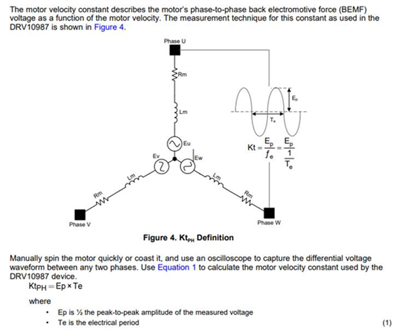
3.Flux : estimation is 0.021V/Hz. How could I measure it with instruments to check if the value is correct ?

I attached a screenshot of software for information. 

Thank you in advance !

  • Hi Sebastien,

    Thanks for your questions! I have a few questions to get a better understanding and to check possible causes:

    1. Would you be able to provide the datasheet for your motor?

    2. Does the motor spin during the motor identification process? If so, does it spin very rough, or is it a steady smooth spinning? The rotor should spin during most of the identification process as it is calculating the various parameters.

    3. Have you tried tweaking the resistance estimation current to see if that improves the identification parameters? 

    4. What is the context of "ut resistance"? is this a spec in the datasheet? The 2 conventions for phase naming that I have seen are A,B,C and U,V,W, so I believe that ut resistance is referring to something else.

    5. Using a sin wave to calculate the inductance is a valid way to estimate the inductance of the motor. You could also use an LCR meter to measure the inductance and compare the results. 4 micro Henry seems quite low, though I am not as knowledgeable in what a reasonable inductance value would be for a small motor so it may be correct.

    6. The Rs value is the phase resistance, so for a wye wound motor if the datasheet provides the line to line resistance, the Rs value should be about half that value.

    Regards,

    Anthony Lodi

  • 1. Here is the picture of the datasheet of the motor I use. (Axi 2814/10).

    2. Sometimes the motor does not move at all during estimation, sometimes it makes some small movements. In all case, it never spin. 

    3.I did not change parameters because the process seems not easy (need to compile firmware?). So I would like to measure all parameters before modifying the .h file.

    4. Sorry for the misunderstanding, it is well naming A B C.

    5. I will check my inductance measurements. 4 micro henry is certainly too low...

    6.Ok with that. Datasheet indicate the line to line resistance so I need to take half.

    => My most important question is : how to measure the flux parameters ?

    After measuring flux, I will change the .h file.

    Thank you:)

  • Hi Sebastien,

    I will get back to you on the flux question, I am not sure on how to calculate that.

    Have you tried adjusting the parameters shown below to see if that improves the identification process? If you hover over the question mark symbols that will give more information on how to adjust these parameters. Your description of the operation of the motor during motor identification indicates to me that the parameters shown below may need to be adjusted to provide proper motor identification.

    Unfortunately it doesn't look like there is a lot of information available on the specs of the motor, it would have been nice if in the datasheet the inductance was also listed as well as the number of pole pairs.

    Regards,

    Anthony Lodi

  • Hi Sebastien,

    I was able to get information on calculating flux. The units for flux is V/Hz, and describes the relationship between the BEMF voltage generated by the motor and the speed of the motor. To calculate the flux you can follow the steps outlined below:


    This information is found in the DRV10987 tuning guide, but the information is still valid for the flux calculation in your situation.

    Regards,

    Anthony Lodi

  • Thank you Anthony ! 

    We measured our motor : 100mV peak to peak at 10Hz. So 0,005V/Hz.

    Another question (maybe simple, but i do not a clear explanation).

    Our motor has 12 poles (4x3).

    So what should be the pole pair value for this motor ? 

    4 or 6? (Estimation done by soft is 4 but I have doubt).

    Thank you 

  • Hi Sebastien,

    the number of pole pairs on a motor is the number of permanent magnet north/south pole pairs that are present on the rotor of the motor. This is different than the number of phase windings present. From what I can tell your motor seems to have 14 poles (based on some brief research I did on the motor), which would be 7 pole pairs, but you may want to double check for yourself to see if you can find the number of poles for your motor online. 

    I would be interested to see if correctly adjusting the "pole pairs" to 7 in the GUI will help improve motor identification. 

    Regards,

    Anthony Lodi

  • Hi Anthony, thank you for your help !

    I confirm : my motor has 14 magnets, so I configured 7 "pole pairs".

    I changed to 7 "pole pairs" and tried several times (4 or 5 times) a motor identification : unfortunately, the card always turned into fault mode (red led).

    And now, I'm unable to connect to the card Confused (Even after reinstalling the software).

    What could I have done wrong ?

    I spent a lot of time (woth 2 different cards) but I can't get this card to work...

    I Do you have an idea why ?

    I'm thinking about switching to another infineon solution, maybe I will have more luck.


    Sebastien

  • Hi Sebastien,

    Sorry to hear about the issues you are facing, is it the same issue that you were having with the hardware board connecting? Could you send the error log when you try to connect? You can do this by pressing F10 while on the GUI and then selecting inspect and going to the console view. If you can refresh the GUI after opening the console view that would be helpful. 

    You could also try using Code Composer Studios (CCS) to run code on the device instead of using the GUI to see if you have any issues connecting. Instructions on how to do this can be found in the below document.

    https://www.ti.com/lit/ug/slvubh8b/slvubh8b.pdf?ts=1648667584718

    If you still cannot connect to the F28027 in CCS then that could indicate that there is some damage that has occurred to the F28027 that is causing it to fail to connect. If you can connect to CCS and flash the code onto the device but cannot connect to the GUI, then there may be a different issue that is occurring. 

    One possibility could be that there is some ESD damage that could be occurring in your setup that could be causing these issues. 

    Regards,

    Anthony Lodi

  • Hi Sebastien,

    Have you been able to resolve the issues you were facing? Is there any more help that you need?

    Regards,

    Anthony Lodi