Other Parts Discussed in Thread: TMS320F28035, CONTROLSUITE
I've recently bought the DRV8303EVM evaluation module and, at first, I wanted to use the InstaSpin GUI but I couldn't connect the board to the GUI. I've installed the driver which I downloaded from the TI website page (https://www.ti.com/tool/DRV8303EVM?keyMatch=&tisearch=search-everything&usecase=hardware) but still the connection fails.
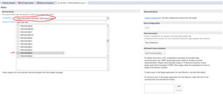
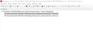
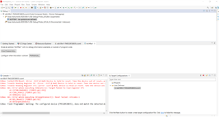
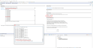
I've then tried to connect the board to CCS version 11.1 and I went through the target configuration as explained in the pdf User Guide but again the configuration fails and it gives me the error message in the attached txt file.
Could you please help me with that?
thank you!
[Start: Texas Instruments XDS100v1 USB Debug Probe_0]
Execute the command:
%ccs_base%/common/uscif/dbgjtag -f %boarddatafile% -rv -o -F inform,logfile=yes -S pathlength -S integrity
[Result]
-----[Print the board config pathname(s)]------------------------------------
C:\Users\GIORGI~1.VAL\AppData\Local\TEXASI~1\
CCS\ccs1110\0\0\BrdDat\testBoard.dat
-----[Print the reset-command software log-file]-----------------------------
This utility has selected a 100- or 510-class product.
This utility will load the adapter 'jioserdesusb.dll'.
The library build date was 'Dec 8 2021'.
The library build time was '11:16:32'.
The library package version is '9.6.0.00172'.
The library component version is '35.35.0.0'.
The controller does not use a programmable FPGA.
The controller has a version number of '4' (0x00000004).
The controller has an insertion length of '0' (0x00000000).
This utility will attempt to reset the controller.
This utility has successfully reset the controller.
-----[Print the reset-command hardware log-file]-----------------------------
The scan-path will be reset by toggling the JTAG TRST signal.
The controller is the FTDI FT2232 with USB interface.
The link from controller to target is direct (without cable).
The software is configured for FTDI FT2232 features.
The controller cannot monitor the value on the EMU[0] pin.
The controller cannot monitor the value on the EMU[1] pin.
The controller cannot control the timing on output pins.
The controller cannot control the timing on input pins.
The scan-path link-delay has been set to exactly '0' (0x0000).
-----[The log-file for the JTAG TCLK output generated from the PLL]----------
There is no hardware for programming the JTAG TCLK frequency.
-----[Measure the source and frequency of the final JTAG TCLKR input]--------
There is no hardware for measuring the JTAG TCLK frequency.
-----[Perform the standard path-length test on the JTAG IR and DR]-----------
This path-length test uses blocks of 64 32-bit words.
The test for the JTAG IR instruction path-length failed.
The JTAG IR instruction scan-path is stuck-at-zero.
The test for the JTAG DR bypass path-length failed.
The many-ones then many-zeros tested length was 1 bits.
The many-zeros then many-ones tested length was 2048 bits.
-----[Perform the Integrity scan-test on the JTAG IR]------------------------
This test will use blocks of 64 32-bit words.
This test will be applied just once.
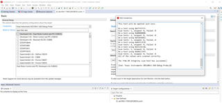
Do a test using 0xFFFFFFFF.
Test 1 Word 0: scanned out 0xFFFFFFFF and scanned in 0x00000000.
Test 1 Word 1: scanned out 0xFFFFFFFF and scanned in 0x00000000.
Test 1 Word 2: scanned out 0xFFFFFFFF and scanned in 0x00000000.
Test 1 Word 3: scanned out 0xFFFFFFFF and scanned in 0x00000000.
Test 1 Word 4: scanned out 0xFFFFFFFF and scanned in 0x00000000.
Test 1 Word 5: scanned out 0xFFFFFFFF and scanned in 0x00000000.
Test 1 Word 6: scanned out 0xFFFFFFFF and scanned in 0x00000000.
Test 1 Word 7: scanned out 0xFFFFFFFF and scanned in 0x00000000.
The details of the first 8 errors have been provided.
The utility will now report only the count of failed tests.
Scan tests: 1, skipped: 0, failed: 1
Do a test using 0x00000000.
Scan tests: 2, skipped: 0, failed: 2
Do a test using 0xFE03E0E2.
Scan tests: 3, skipped: 0, failed: 3
Do a test using 0x01FC1F1D.
Scan tests: 4, skipped: 0, failed: 4
Do a test using 0x5533CCAA.
Scan tests: 5, skipped: 0, failed: 5
Do a test using 0xAACC3355.
Scan tests: 6, skipped: 0, failed: 6
Some of the values were corrupted - 74.5 percent.
The JTAG IR Integrity scan-test has failed.
-----[Perform the Integrity scan-test on the JTAG DR]------------------------
This test will use blocks of 64 32-bit words.
This test will be applied just once.
Do a test using 0xFFFFFFFF.
Test 1 Word 0: scanned out 0xFFFFFFFF and scanned in 0xFFFFFFFE.
Scan tests: 1, skipped: 0, failed: 1
Do a test using 0x00000000.
Test 2 Word 0: scanned out 0x00000000 and scanned in 0x00000001.
Scan tests: 2, skipped: 0, failed: 2
Do a test using 0xFE03E0E2.
Test 3 Word 0: scanned out 0xFE03E0E2 and scanned in 0x00000000.
Test 3 Word 1: scanned out 0xFE03E0E2 and scanned in 0x00000000.
Test 3 Word 2: scanned out 0xFE03E0E2 and scanned in 0x00000000.
Test 3 Word 3: scanned out 0xFE03E0E2 and scanned in 0x00000000.
Test 3 Word 4: scanned out 0xFE03E0E2 and scanned in 0x00000000.
Test 3 Word 5: scanned out 0xFE03E0E2 and scanned in 0x00000000.
The details of the first 8 errors have been provided.
The utility will now report only the count of failed tests.
Scan tests: 3, skipped: 0, failed: 3
Do a test using 0x01FC1F1D.
Scan tests: 4, skipped: 0, failed: 4
Do a test using 0x5533CCAA.
Scan tests: 5, skipped: 0, failed: 5
Do a test using 0xAACC3355.
Scan tests: 6, skipped: 0, failed: 6
Some of the values were corrupted - 67.2 percent.
The JTAG DR Integrity scan-test has failed.
[End: Texas Instruments XDS100v1 USB Debug Probe_0]