This thread has been locked.

If you have a related question, please click the "Ask a related question" button in the top right corner. The newly created question will be automatically linked to this question.

DRV10975: RM definition

Part Number: DRV10975
Other Parts Discussed in Thread: MCF8316A

Hello,

Our customer asked about DRV10975 RM parameter related questions .Please give him answer and comments about his questions in below.

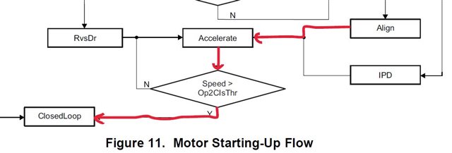
1. He found motor rotation stop at the beginning of the rotation in case he sets slightly higher RM value e.g. RM=5.6ohm against RM=4.7ohm  in typical. Do you tell him any particular point or phenomenon to check more in the evaluation.

2. Could you also tell him specific parameters that impact on this issue or which characteristics check carefully.

3. He found out analog speed control response delay when he optimized the lead angle. Could you tell him any potential reason why the analog speed control response was delayed.

Best regards,

  • Hi Toshiro,

    1. When higher Rm is programmed, device applies lesser voltage to the motor terminals based on the open loop current limit. This could cause the motor not to start successfully due to insufficient current. 

    2. We recommend programming the correct Rm and then tweak the lead time with change in motor speed.

    3. Do you see this delay during startup or does it take more time for the motor speed to settle down?

    Regards,

    Vishnu

  • Hi Vishnu,

    Thank you very much for your feedback.

    While the customer has tested with new OpenCurr parameter 1.6A instead of previous 0.8A openCurr, his issue was resolved even if RM=5.64ohm.

    In addition to this, he also found out the motor operation works normally in case he sets Op2ClsThr=0x1f (204.8Hz) instead of 0x15 (76.8Hz). Then he asked about the condition transition to Closed loop from open loop. Do we understand that the condition is Speed>Op2ClsThr as presented in the datasheet Figure 11 and 18. Please let us know if there are the other condition.

    He has another question.

    Would you also help him out if he is able to change RM value after transition to closed loop or after motor start up.

    Best regards,

  • Toshiro-san,

    Yes, you are right. Device enters closed loop when the speed is above open-to-closed loop threshold. Yes, I can work with the customer to resolve this issue.

    Regards,

    Vishnu

  • Hi Vishnu,

    Thank you for your reply.

    Do you have any way to know the motor control turns to closed loop. The customer should read Motor Spped1,2 then see if it is larger than Op2ClsThr value ? please let us know, if you knows easier way, because he have to see if there is any problem while the motor system transition from open loop to closed loop.

    Based on the evaluation result, would you think the customer should change the Op2ClsThr value ?

    He would like to change RM value after transition to closed loop or after motor start up, though I know we do not recommend programming incorrect RM. If it have potential problem, please tell him what will be happened. Would you also clarify what kind of the other issues are going to be happened if he programs larger RM instead of motor spec.

    Best regards,

  • Toshiro,

    You can configure FG to "Output FG in closed loop only". By doing this, FG will start outputting pulses immediately after the device enters closed loop.

    Setting the open to closed loop threshold depends on the BEMF of the motor. You can set a higher threshold if motor has low BEMF constant. My explanation on Rm remains the same as previous posts.

    Regards,

    Vishnu

  • Hi Vishnu,

    Thank you very much for your suggestion.

    I had a discussion with the customer today. The customer understood correct RM=4.7ohm must be applied in his application. On the other hand, he is anxious about the cases of that actual phase resistance is shifted due to motor deviation, ambient temperature, board layout.
    This is the reason he has tested by slightly larger RM like RM=5.64ohm, 6.11ohm and check carefully open loop to closed loop transition in following paths. The customer issue in these condition was unstable FG frequency at the transition point from Open to Closed loop.

    The customer requirement is

    - How to improve unstable FG phenomenon at Open to Closed loop transition. Could you help him out which parameters are able to improve.

    - What kind of characteristic must be checked in his evaluation.

    - Could you also support a way of seamless and quick transition from open to closed loop.

    Best regards,

  • Toshiro,

    I'll get back to you on Monday

    Regards,

    Vishnu

  • Toshiro,

    DRV10975 is a sensorless driver. Commutation logic is based on the accuracy of the programmed motor parameters. Since the variation in Rm is 20% - 30%, device might not be able to estimate the BEMF zero crossings accurately.

    We have MCF8316A in our portfolio which is a newly released IC. This is a single-chip, code-free sensorless FOC solution which can address the issue related to jump in speed or motor parameter variation effects. Can you check if the customer is interested in this part? Below is the link to the datasheet.

    https://www.ti.com/lit/ds/symlink/mcf8316a.pdf

    Regards,

    Vishnu

  • Hi Vishnu,

    I am sorry. What the customer needs to know is 1) the way to improve seamless and quick transition from open loop to closed loop, 2) what kind of the characteristics he focuses on the start up evaluation.

    Would you think following transition makes seamless and quick transition to closed loop. If this is the right way, please let him know which kind of performance should the customer has to check.

    Best regards,

  • Toshiro-san,

    1) the way to improve seamless and quick transition from open loop to closed loop

    Quick transition from open to closed loop can be achieved by minimizing the align time, increasing open loop acceleration constants A1, A2 and setting a lower open to closed loop threshold.

    2) what kind of the characteristics he focuses on the start up evaluation.

    I'm not sure how this question is different from the previous one. Following the above recommendations should help minimize the startup time. 

    The red arrow that you marked is the path to transition to closed loop,

    Regards,

    Vishnu