Other Parts Discussed in Thread: BOOSTXL-DRV8323RH, DRV832X,
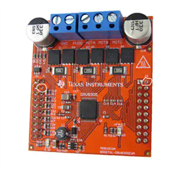
I bought your BOOSTXL-DRV8323RH. I supply DC voltage 30[V] and gate input 0-5[V](INHA, INLA) but it does not work.
Is there any missing input?
Original question:

I bought your BOOSTXL-DRV8323RH. I supply DC voltage 30[V] and gate input 0-5[V](INHA, INLA) but it does not work.
Is there any missing input?