This thread has been locked.

If you have a related question, please click the "Ask a related question" button in the top right corner. The newly created question will be automatically linked to this question.

DRV8300DRGE-EVM: DRV8300DRGE-EVM

Part Number: DRV8300DRGE-EVM
Other Parts Discussed in Thread: DRV8300
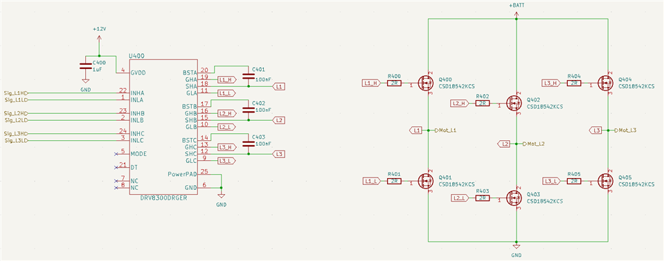
We are having some trouble using the DRV8300DRGE to drive a BLDC motor (schematic shown below). We are using a 12V GVDD supply with a battery voltage of ~40V. I'm not sure if we are misinterpreting the datasheet but it seems like our high side gate outputs never actually turn off even when their inputs are grounded. The datasheet shows a high-side gate low level voltage of 0-0.35V but we are seeing about 10.5-11V when the high-side input is grounded or left open (grounded through internal 200k pulldown). It seems like this 10.5-11V is keeping the high side in a partially on state where current leaks through when the low side is active. On one of the samples tested, turning on the low side of phase A does bring the phase A high-side gate drive down to 0V, however, phases B and C don't do the same and grounding the high side inputs seems to have no effect on any phase with the gate drive voltage staying around 10.5-11V. Could you please inform us if we are interpreting something wrong or if there is an error in the schematic?
  • Hi Dan,

    What is the battery voltage? Ensure that when you measure the high side gate, you are measuring with respect to the high-side source (SHx). If SHx is 10.5V-11V, then the DRV8300 keeps GHx to 10.5-11V to ensure a VGS voltage of 0V for the high side FETs. 

    When switching the half bridge, are you using synchronous rectification to refresh the bootstrap capacitors? When INLx = high, the bootstrap caps should charge to GVDD. Is there enough INLx on time to ensure the bootstrap caps fully charge?

    Are the caps rated correctly in voltage? They should be rated for 1.5x to 2x their DC bias voltage, so for instance, the boostrap caps should be rated for at least GVDD*2 = 25V to ensure its effective capacitance. 

    You may also want to consider an external Rgs pulldown resistor (10k to 100k) after the series gate resistors to try and pulldown the gates harder. 

    If none of the suggestions work, we may want to review layout as a next step.

    Thanks,
    Aaron

  • Hi Aaron, 
    Thank you for the support. You are correct, the gate voltages were staying at 0v relative to the high-side source rather than 0v relative to gnd. I think the other issues we saw were just due to a mistake in wiring, our latest sample is working perfectly now.
    Thanks again for the help.
  • Thanks Dan! 

    Appreciated on the update, and glad to hear that your setup is working now 

    Best Regards, 
    Andrew