This thread has been locked.

If you have a related question, please click the "Ask a related question" button in the top right corner. The newly created question will be automatically linked to this question.

BOOSTXL-DRV8323RS: Current sensing waveform

Part Number: BOOSTXL-DRV8323RS

Hello, I have a BOOSTXL-DRV8323RS interfaced with a Nucleo board, driving a BLDC motor. It is set to 1X PWM mode and runs smoothly in either open- or closed-loop control.

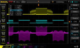
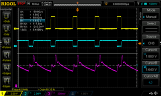
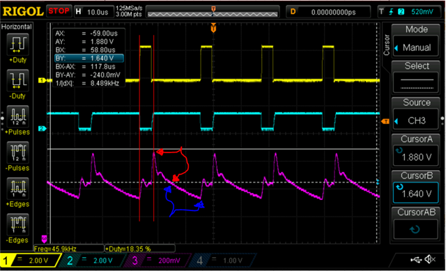
I'm now working on current sensing but the ISEN output waveform is different from the expected quasi-square wave. Any ideas on possible reasons for this/potential fixes? Thanks in advance

Displayed below are MOTA, GLA, and ISENA

  • Hi Josh,

    Thank you for your question! 

    The CSA outputs are only valid for measuring the current through a phase during the time when the low side MOSFET is on since when the low side MOSFET is off the shunt resistor that is used for current monitoring is not connected to the motor phase. For example, the region that is between the two red lines in the image below should be ignored, since the low side MOSFET is off in this region. In the region where the low side MOSFET is on, you can see that the current is flowing out of the phase (current flowing from ground through the low side MOSFET and out of the phase, region indicated by red arrows) which is expected. When the high side FET is on, this produces current flowing out of the phase, and then when the high side MOSFET is turned off the current starts to decay through the low side MOSFET. It looks like you may be using a low inductance motor because the current through the phase decays all the way to 0. The higher the current in the phase and the higher the inductance of the motor, the longer it will take for the current to decay. Once the current flowing out of the phase decays to 0, then the current begins flowing into the phase (current flowing into the phase, through the low side MOSFET to ground, region indicated by blue arrows). The reason that current begins to flow into the phase is likely due to the momentum of the rotor causing the permanent magnets on the rotor to generate a current in the winding for that particular phase. Once the high side MOSFET turns back on, the VM voltage is again applied to the phase and current again begins to flow out of the phase and the process repeats. 

    If you are still concerned that the CSA outputs aren't accurate, I would recommend using a current probe on the phase and compare it to the CSA outputs to see if the shape of the current waveform is similar. 

    If you increase the duty cycle to a higher duty cycle, that will likely result in the current in the motor windings being high enough to not completely decay during the period when the low side MOSFET is on. 

    Regards,

    Anthony Lodi

  • Hey Anthony, 

    Alright, I think this is starting to make sense for me now. I appreciate your answer!

  • Hi Josh,

    Great to hear! 

    Regards,

    Anthony Lodi