Dear community, I have a basic question on DRV8871, as I am new to this component.
I would like to drive a DC motor with it (in the forward direction only). Using the PWM signal coming from a micro-controller.
- Question 1:
Now, I see that the IC has two inputs IN1 and IN2, and I do not clearly understand how I should apply the PWM. (my understanding is that one of this PINs gets a constant voltage either 0V or 5V for instance, and the other pin receives the PWM signal)
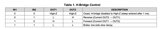
from table 1 below, my understanding is that the signals should be as per the bottom two rows of the table, with IN1=1 IN2=0 to drive the motor forward, and IN1=1 IN2=1 when the voltage to the armature is set to zero and the motor works in free-wheel operation (i.e. armature inductance discharges its energy through the free wheel diode).
If this is correct, then IN1 is always = 1 and therefore I can just connect it to the +5V of my microcontroller. IN2 is the pin where the PWM coming from my microcontroller is applied, and in turn (here is where I am confused) when the PWM output on Pin IN2 is low, the motor is actually driven forward, while when the PWM on pin IN2 is high the motor is breaking (current is free wheeling). Therefore the duty cycle of a standard trailing edge PWM would be such that a high duty cycle (IN2 mostly at 1) will mean slow speed and a low duty cycle, IN2 mostly at 0, will mean a high speed of the motor (which is a bit counter intuitive). Would be great if you can confirm that my understanding is corrector not (i.e. high motor speed = low duty cycle on PWM given on IN1).
Also, is the condition with IN1 =0 and IN2 =0 ever relevant? (I am using a PWM with 980 Hz frequency)
- Question 2
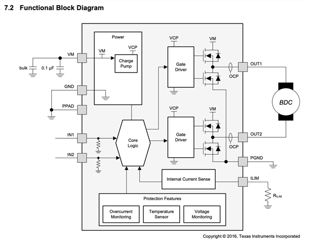
Is PGND in Fig. 7.2 the "power" ground? i.e. the DC motor ground? which is different from GND in Fig. 7.2, which is to be connected to the microcontroller ground?
Thanks for your help
Leo