Because of the holidays, TI E2E™ design support forum responses will be delayed from Dec. 25 through Jan. 2. Thank you for your patience.

This thread has been locked.

If you have a related question, please click the "Ask a related question" button in the top right corner. The newly created question will be automatically linked to this question.

DRV8303: Sensorless DC motor drive scheme

Part Number: DRV8303

Hi team,

Here's an issue from the customer may need your help:

The customer would like to drive a sensorless DC motor with the DRV8303 or the same chip, is there any recommend schemes available? 

Could you help check this case? Thanks.

Best Regards,

Cherry

  • Hi Cherry,

    We'll get you a reply on Monday as today is a TI Holiday.

    Thanks,
    Aaron

  • Hi Cherry,

    Thanks for the question! I want to confirm that when you say sensorless DC motor you are referring to a sensorless brushless DC motor and not a brushed DC motor, is that correct?

    Regards,

    Anthony Lodi

  • Hi Anthony Lodi,

    Thanks for your help.

    I want to confirm that when you say sensorless DC motor you are referring to a sensorless brushless DC motor and not a brushed DC motor, is that correct?

    Yes, correct.

    Thanks and regards,

    Cherry

  • Hi Cherry,

    Thanks for confirming! Is the customer intending to use sensorless FOC control or sensorless Trapezoidal Control? The DRV8303EVM may be a good place to start, since it can also support a couple sensorless solutions using Firmware from the DRV8301-HC-C2-KIT. More details on running the sensorless firmware on the EVM can be found in section 5 of the DRV8303EVM User's Guide. The customer can download the DRV8303EVM schematic from the DRV8303EVM page to use as a reference for their design. The EVM also can support sensored control, so there will be some portions of the schematic that will only apply for sensored control. 

    Regards,

    Anthony Lodi

  • Hi Anthony Lodi,

    Thanks for your response!

    And the customer also have a question:

    Add a back-EMF over zero comparison circuit to the device. Compare the port voltage from the oscilloscope with the center point voltage, the waveform is not as expected, so it is not sure if it can be captured by the control mcu. Is there any routine for this?

    Thanks and regards,

    Cherry

  • Hi Cherry,

    Is the customer using trapezoidal control or sinusoidal/FOC control? The measuring of the back-EMF for trapezoidal control is simpler since there will always be one phase that is Hi-Z and that phase can be used for calculating the back-EMF. For sinusoidal or FOC control, calculating the back-EMF is more complex due to the fact that all 3 half-bridges are always switching. As a result, it is necessary to know some of the motor parameters to properly calculate the back-EMF when using FOC or sinusoidal control.

    Regards,

    Anthony Lodi

  • Hi Anthony Lodi,

    Sorry for the late action and I've just got the response from the customer today:

    They are using Square wave control and back-EMF for trapezoidal control for comparison. 

    https://e2echina.ti.com/cfs-file/__key/communityserver-discussions-components-files/121/_CD533575A852BF52_.docx

    Please see the link above, is everything ok? Is there anything needed to be aware of?

    Thanks and regards,

    Cherry

  • Hi Cherry,

    I have a few questions to help me better understand the waveforms:

    1. What is the motor supply voltage that is being used?

    2. The first 3 waveforms show really small amplitude waveforms of less than 1V. At what point on the board is each of these waveforms being measured at? Could you indicate where they are probing on the schematic? 

    3. The last 7 pictures show amplitudes of around 6V. Where is this being measured? Could you indicate on the schematic where each picture is being probed?

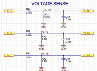
    4. There are 2 snippets of schematics in the document showing the phase voltage sensing. Both schematics show a different configuration and different component values. Which one is the customer using? What is the purpose of showing 2 snippets with different configurations?

    Regards,

    Anthony Lodi

  • Hi Anthony Lodi,

    1. What is the motor supply voltage that is being used?

    18V.

    2. The first 3 waveforms show really small amplitude waveforms of less than 1V. At what point on the board is each of these waveforms being measured at? Could you indicate where they are probing on the schematic? 

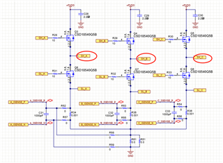
    The first 3 waveforms are being measured at the following point highlighted:

    3. The last 7 pictures show amplitudes of around 6V. Where is this being measured? Could you indicate on the schematic where each picture is being probed?

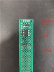
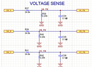
    There is currently no central point of comparison in the schematic, and the VA-FB,VB-FB,VC-FB in the following figure are wired out of the access resistance, simulating a central point of comparison as shown in Figure a. Compare with a comparator.

    Figure a(The Chinese on the diagram means from top to bottom are: External analogue center point; comparator; Three-phase voltage)

    4. There are 2 snippets of schematics in the document showing the phase voltage sensing. Both schematics show a different configuration and different component values. Which one is the customer using? What is the purpose of showing 2 snippets with different configurations?

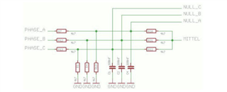
    Figure c is used (Figure 4 is a reference diagram, and the center comparison point is not currently shown in the schematic, but is physically modeled as Figure b, and the VA-FB,VB-FB, VC-FB is wired out of the access resistor, simulating a central comparison point)

    Figure b

    Figure c

    And please be noted that the document I given in my last reply is the compare circuits, and the compared waveforms.

    Q: Can this be used for real applications? What more debug is needed?

    Thanks and regards,

    Cherry

  • Hi Cherry, 

    You mention that the supply voltage is 18V and that the first 3 waveforms are measured at the SH_x nodes, however I am seeing the SHx voltage not going above 1.5V as well as the SHx voltage not going all the way to ground. A proper waveform would show SH_x going all the way to 18V when the high side MOSFET is on, and going all the way to GND when the low side MOSFET is on. The waveforms that the customer provided don't seem to show that the MOSFETs are switching correctly. Am I missing something regarding the first 3 waveforms? If not, would the customer be able to provide the GHx and GLx waveforms along with SHx to see if the MOSFETs are switching properly?

    Regards,

    Anthony Lodi

  • Hi Cherry,

    Just wanted to follow up on this to see if there is any update in light of my previous reply.

    Regards,

    Anthony Lodi

  • Hi Anthony Lodi,

    I haven't got any follow up on the previous reply from the end customer and once got anything new I will update ASAP.

    Thanks and regards,

    Cherry

  • Hi Cherry,

    Thanks for the update!

    Regards,

    Anthony Lodi