This thread has been locked.

If you have a related question, please click the "Ask a related question" button in the top right corner. The newly created question will be automatically linked to this question.

DRV8353: Current sensing for 1-shunt

Part Number: DRV8353

Hi,

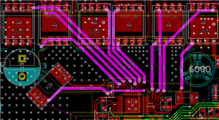
Is there any specific layout or method for 1-shunt current measuring?

I want to know the how to sense current using 1-shunt resistor.

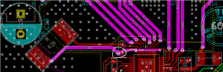
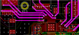
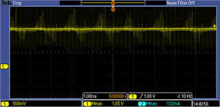
I connect SPC and SNC with shunt resistor. and I check the SOC signal.

SOA and SOB were not connected.

SPA, SPB, SNA, SNB were connected to GND.

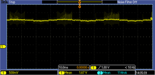
SOC signal is shown in the figure below.

motor commutation was based on the hall sensor. So there is no current feedback for motor control.

I can not measure the current signal.

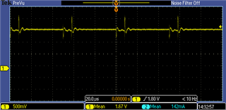
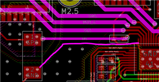
I compared the SOx signal with 2-shunt board. In this case DRV8323H was used.

For 2-shunt signal(SOx) is shown below figure.

you can see the current form.

  • Hi Min-su,

    Is there a CSA low-pass filter at the SOC output? There appears to be a lot of switching noise on your SOC waveform. We recommend placing a low pass RC filter at the CSA output next to the MCU ADC pins to filter switching noise, usually a cutoff frequency of at least 10x the PWM frequency. 

    For the layout of SNC, does this go to the top layer pad here?

    Thanks,
    Aaron

  • Hi Arron,

    there is a low-pass filter at the SOC output.

    2200pF and 56ohm.

    there is no layout of SNC on the top layer.

    But, there is a inner layer with copper pour for SNC.  The inner layer is GND.

    Could that be the cause?

    Or should I connect the SPx to shunt directly without copper pour layer?

    For 2-shunt circuit, I connected SNx to GND with cooper layer.

    and I connected SPx to shunt resistor with trace without copper pour.

  • Hi Min-su,

    SNC should be connected via a copper trace from the sink end of the shunt to the SNC pin. You should not connect SNC directly to GND. SPC/SNC should be routed as a Kelvin connection from the shunt resistor to the SPC/SNC pins. 

    Thanks,
    Aaron

  • Hi, Arron.

    I have to change the PCB design.

    And is there any points to check for 1-shunt dc current sensing?

    Thank you.

  • Hi Min-su, 

    For a workaround, since SNC is at the corner of the IC, you can add a small wire from there to the pad of the resistor where SNC should be connected, this will be a low impedance direct connection to the shunt and you should be able to measure the SOC output voltage more effectively. 

    Depending on the number of probes you have, the best places to check for the accuract of 1-shunt DC current sensing are:

    • SPC-SNC as close as possible to the IC (use a math channel to subtract difference and get the differential voltage
      • Probing at shunt can yield different results if there is inductance on SPC/SNC traces
    • SOC as close as possible to the IC (this should be your SPC-SNC differential voltage times the CSA gain setting), subtracted from VREF/2
    • VREF to ensure it is a stable reference voltage

    Thanks,
    Aaron

  • Hi Arron,

    I tried to connect between SNC and shunt directly with wire, but it didn't help.

    The method was helpful, when I designed with 3-shunt. But 1-shunt case was not.

     I think I should change PCB design.

    Thank you.

  • Sorry it did not help with 1-shunt. You can change with PCB design. 

    Thanks,
    Aaron

  • Thanks for your comment.

    Thanks,

    MinSu