Hello,
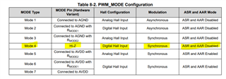
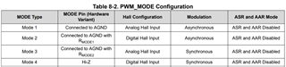
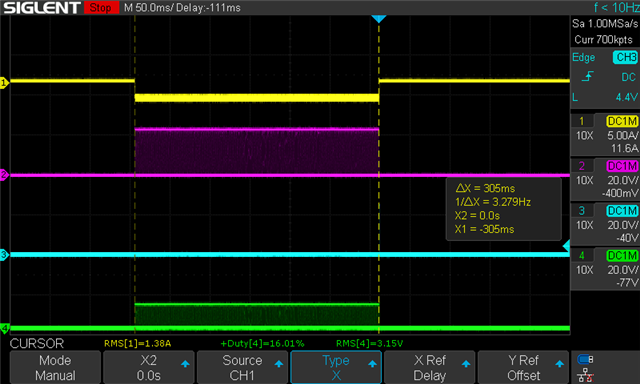
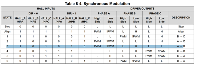
I am testing this eval with Asynchronous rectification with analog Hall (PWM Mode 1) and it is somehow working as expected (motor spinning) with my digital hall motor. (HNx all floating with pullups on HPx). However, when I switch to Asynchronous rectification with digital hall (PWM Mode 2), it works intermittently. As in, I apply a PWM and it works, and then I apply 0 PWM and apply a PWM again, and sometimes it works, sometimes it doesn't. Once it doesn't work, it won't work ever again until PWM mode is switched to mode 1 and back to mode 2...
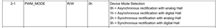
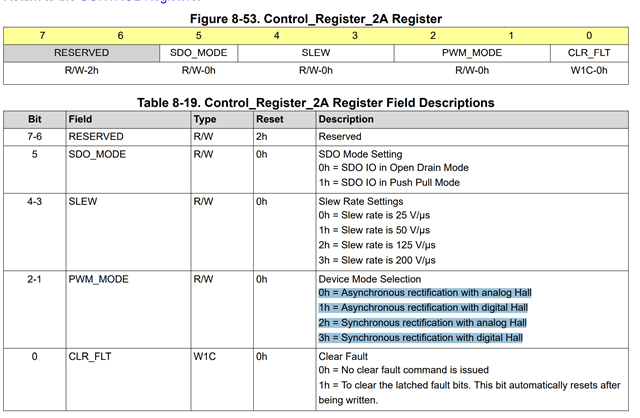
Can I get a confirmation that Control Register 2A is properly documented?:
Thanks,
Jerome