I've been working on a design using the MCF8316A to spin a custom sensorless BLDC motor with a magnetic suspension bearing. I have tried to spin three different motor coil designs:
A: R = 1.6Ω, L = 13μH, Ke = 6mV/Hz (I think...)
B: R = 2.4Ω, L = 62μH, Ke = 3mV/Hz
C: R = 5.3Ω, L = 180μH, Ke = 5.1mV/Hz
Of these, it seems I can only successfully spin design B. It spins both with the magnetic suspension and on a test fixture with a mechanical bearing. It works consistently with low power consumption and we are satisfied with overall performance. The other two designs never successfully reach closed loop control. They tend to spin up in open loop drawing high current, then fault. Sometimes after the fault they will stick in a high current draw state (several amps) until unplugged. Design A is from an older iteration of the project that spins just fine with a simpler trapezoidal controller.
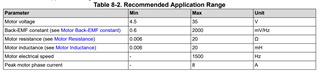
My question is: what could be the difference? These are all within the recommended application range from table 8-2 of the datasheet, so I would expect that they would all work or none would:
The R and L values are measured directly with a meter and the Ke values are measured using a scope on two channels as specified in figure 5 of the guided tuning section of the dev kit GUI:

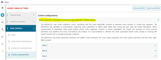
MPET never worked correctly for me, even with design B. It would correctly measure R and L, but never arrive at a Ke value. Measuring them manually and entering the values in the right registers using the dev kit worked for me after I was told on this forum that you also have to set SPD_LOOP_KP and SPD_LOOP_KI manually to disable MPET. I am setting them to 10 and 1 respectively which is what was recommended to me. Could those values be wrong in such a way that prevents closed loop control from working? What could be causing MPET to fail for Ke?
Am I missing something? Is there anything that could be different about the coil designs other than what I have shown here? They are hand-wound very carefully under a microscope. Could slight phase-to-phase asymmetry cause this sort of behavior?
Any information would be appreciated. Thanks,
Mitcham Tuell