This thread has been locked.

If you have a related question, please click the "Ask a related question" button in the top right corner. The newly created question will be automatically linked to this question.

DRV8301: Damp the EMC-radiation of a sinus-driven brushless motor by a commom-mode-choke

Part Number: DRV8301

Dear support team and forum members,

Object of my thread is a circuit which drives a small brushless-motor with low inductivity by a sinus-PWM with 42kHz. The space vector of the TMS320-µC alternates every PWM period from GND to VSS (even when the zero-vector would not alternate in idle mode - the logarithmic concept of EMC would not make the disturbing sent waves significantly smaller). The generated low-frequency is spreaded by a necessary motor-cable from 1 and a half meter length into the air. Furthermore 3 single chokes increase the inductivity of the motor coils to enable feedback of the motor state to be calculated by the µC. At one hand these single chokes, combined with capacitors, act as a low pass but on the other side the low passes can not be sufficiently dimensioned to damp the low-frequency spread-out. Also the lowpass leads to an higher wattles current - warming the single chokes.

About an answer to the following 2 questions I would by happy.

- Is shilding in combination with omitting the low-pass-capacitors better then damping by a common-mode-choke?

- Are there better alternatives to my idea of filtering by the common-mode-choke?

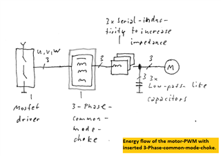
The common-mode-choke solution:

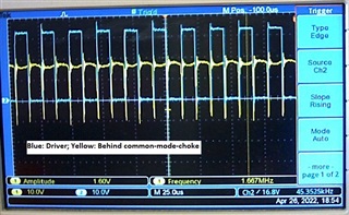
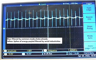
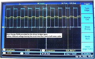
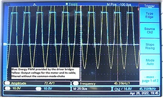
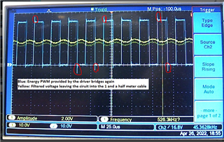
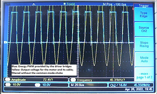
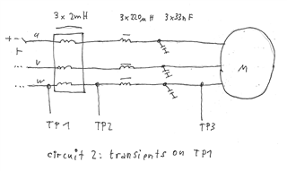
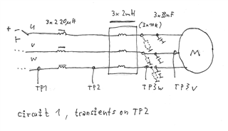
A common-mode-choke is inserted into the energy path which drives the brushless motor. The choke consists of a soft-ferrite ring (see photo) with 3x20 windings and an inductivity of 3x2 mH combined with capacitors of 3x33 nF. Like shown in the screenshots first the common mode choke filters the zero-vector of the sinus-pwm while the 3 single inductivities flatten the payload-spikes. In this guessed approach (not exactly calculated) low-frequency-EMC is damped except some remaining sinus-voltage and also the wattles-idle-current does no longer play a role.

Best regards

  • Hi Claus, 

    Thanks for posting your question to e2e forum - 

    We will review your question and provide a response soon, aiming to give an answer by early next week 

    Best Regards, 
    Andrew 

  • Hi Claus, 

    Thanks for your patience - 

    From evaluating your information further, I have below comments: 

    • Generally with low-inductance motors, there is the problem of current ripple induced by PWM signals 
    • looking at your scope captures,
      • it looks like the switch node (SHx) waveforms are slightly worse in the common-mode choke case, when it comes to voltage transients. 
      • and the waveform with no common-mode choke, and only filtering looks to be performing well? 
    • General suggestions for filtering & improving signal performance 

    Best Regards, 
    Andrew 

  • Hello Andrew, hello µC-developers,

    To review my post about EMC and the common-mode-choke-trial I measured the not accepted transients with a better grounded probe and also on a circuit with a swapped order of the serial inductivities and the common-mode-choke.

    Circuit 2 shows the first trial with the bad transients:

    Circuit 2 with transients

    TP1 (Driver side) 

    TP1 timezoom

    Circuit 1 with omitted common-mode-choke and nearly no transients:

    Circuit 1, common-mode-choke

    drawn but omitted for this

    measure

    TP1 (Driver side)

    TP1 timezoom

    Circuit 1 with common-mode-choke and nearly no transients plus decreased EMC on the hand-held-cable:

    Circuit 1 with

    common-mode-choke

    TP1 (Driver side)

    TP1 timezoom

    Same circuit, measured on TP2 where the transients now occur (only on passive parts):

    TP2, not damped transients

    ... same with timezoom

    TP2, transients damped

    with 3x10k resistors

    ... same in timezoom

    On the same circuit; measured voltage between two clamps of TP3, which drive the coils of the motor (a small amount of the 45kHz PWM signal still remains):

    TP3 on 3000 rpm

    TP3 on 8300 rpm

    Result: The swapped order of inductivities (see circuit 1) in the energy path moves the transients - coming with the common-mode-choke - away from the driver transistors.

    I want to ask another question too: In case of a motor with a light whight. Can there a PWM supply (45 ... 100 kHz) be measured on a mechanical way at the rotor (with an ultrasonic microphone or a special vibration sensor)? The motor - used for the measured screenshots above - can run with 3ooo ... 42ooo rpm => 50 ... 700 rounds per second.

    Best regards

  • The oscilloscope-screeshots in my post above will not zoom automatically (may be because of the .bmp-format or may be because of the wrapping table). Please use mouse-right-click -> open-graphic-in-new-browser-tab if you want to view the graph larger.

  • Hi Claus, 

    We are not EMC experts and cannot answer questions on how EMC performance will behave with the common-mode choke circuits implemented above. Our parts are designed to support as little inductance as possible at the powerstage, any inductance you add at the motor phases will affect the amount of motor current you can switch when transitioning commutation states. It is also to predict the performance of motor EMI performance when implemented on a breadboard rather than a PCB. 

    We suggest you try simulating the common mode chokes you are implementing to observe the EMI performance of the motor. There are tools for Simulink and PSPICE. 

    Thanks,
    Aaron

  • Although my EMC-issue is not completely solved I have got a hint that helped me to avoid transients on the driver transistors. Thanks also for general hints relating to motors with low inductance.