


Other Parts Discussed in Thread: CONTROLSUITE, , INSTASPIN-BLDC, C2000WARE-MOTORCONTROL-SDK, C2000WARE
Hello,
I've recently bought the evaluation module DRV8303EVM and I got it to work with the InstaSpin_BLDC project in CCS 11. I found the project in: controlSUITE\development_kits\DRV830x-HC-C2-KIT_v105\InstaSPIN_BLDC.
I've followed the instructions in the 8 incremental build levels of the User Guide and I managed to successfully test a BLDC motor. Now I'm trying to better understand the code in the InstaSpin_BLDC project in order to be able to modify/adapt it to my specific requirements.
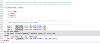
One question I've got is related to the voltage and current measurements using the ADC modules on the TMS320F2803x microcontroller. In the code I can find that the phase voltages are acquired with:
iqVaIn = _IQ15toIQ((AdcResult.ADCRESULT1<<3));
iqVbIn = _IQ15toIQ((AdcResult.ADCRESULT2<<3));
iqVcIn = _IQ15toIQ((AdcResult.ADCRESULT3<<3));
and the current with:
IDCfdbk=-((_IQ15toIQ(AdcResult.ADCRESULT4<<3)-IDC_offset)<<1);
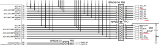
Which to me suggests that voltages of phases A, B and C are capture with the ADC channel ADC-A0, ADC-A1, ADC-A2 and the current with ADC-A4. However, if I look at the schematic of the DRV8303EVM board (see snapshot below and attached pdf) I can see that phase voltage A is connected to ADC-B7, phase voltage B is connected to ADC-A7, phase voltage C is connected to ADC-B4 and the current of phase A (see S01 in the schematic) goes to ADC-A1.
I'm relatively new to CCS, however could you please explain me how the different ADC channels are mapped in CCS? My initial thought was that ADC-A0 (i.e. the 1st ADC channel) would be mapped to AdcResult.ADCRESULT1 but apparently I was wrong.
Thanks
Giorgio

