This thread has been locked.

If you have a related question, please click the "Ask a related question" button in the top right corner. The newly created question will be automatically linked to this question.

DRV8842: Causing a reset on MCU due to drop in 3.3V regulator

Part Number: DRV8842
Other Parts Discussed in Thread: TPS54429,

Hi there,

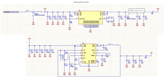
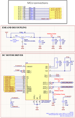
I've got 2x DRV8842's on my board which is powered from a 24V PSU. The IO lines IN1, IN2, I0, DECAY, nRESET, nSLEEP and nFAULT are connected to a 3.3V MCU. The IN1 and IN2 are being on/off driven (no PWM), current limits I0 I4 are set high, DECAY pin is high impedance (input at MCU), nSLEEP is set high, nFAULT is MCU input. The Vref is set using a potential divider from the V3P3OUT with R1=2.7k and R2=5.1k and so VREF is 2.16V giving a max current of 4.32A. 

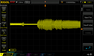
The DRV8842 is driving a linear actuator which runs fine but sometimes I'm seeing a significant dip on the 3.3V voltage regulator. Sometimes it is resetting the MCU due to a brownout reset. The 3.3V SMPS (TI part TPS54429) has a Vin of 12V and output of 3.3V. The dip always occurs when the actuators hit their end stop which is likely a high current point. We're working on preventing the actuator from hitting that mechanical end stop with position sensors and firmware but I still need to get rid of this chance of a voltage dip. Is there some situation that the motor driver loads the MCU pins enough to cause a load large enough to cause a trip on the 3.3V SMPS? Note that the SMPS is capable of providing 4.5A. The MCU is physically quite far away from the motor drivers and so I don't think it's a noise issue. 

Any help you can provide me with will be really useful. Thank you, Louis

  • Hi Louis,

    Thank you for posting to the motor drivers forum.

    Can you provide a block diagram of your power tree. This will help me understand your set-up.

    Regards,

    Pablo Armet

  • Hi Pablo,

    Below is the generation of 3.3V from a 24-12 step down and 12-3.3 step down:

    Also below is the MCU connections and motor driver circuitry:

    Thanks,

  • To add more detail, the motor driver OUT pins connect directly to the actuator. I've now tried powering the MCU from an external 3.3V PSU and I'm still seeing a lot of noise on the 3.3V line even though it's external and not connected to the boards main 3.3V rail (I removed FB3 shown above to isolate and add power). I'm using a ground reference which is across one of the MCU decoupling capacitors and this is what I'm seeing when the actuator gets to the end stop on the 3.3V rail. At best this doesn't cause any known issues but at worst I've seen it reset the MCU. 

    I've not yet tried isolating the incoming 24V from the motor drivers 24V but because it seems like the issue is coupling to the 3.3V line anyway I'm not sure it'll fix things. 

  • Hi Louis,

    Thank for the information. It is very insightful.

    So it looks to me that somehow the noise from the power supply or possibly the motor driver is coupling to the 3.3V supply. I would take a look a the PCB layout in case there is a power trace close to the 3.3V trace.

    Another way to verify this is to remove the 24V supply and see if there is noise on the 3v3 node.

  • Hi Pablo,

    I'll look at the layout a bit more but I can't easily see how this extreme amount of noise >1V pk-pk would be coupled onto the 3.3V line. I've tried isolating the 3.3V, 12V and 24V PSU lines and even the 24V line going specifically to the motor drivers using an external PSU and still see the noise. The only common connection as far as I can see is the ground line. The noise I see is always the same. And I also see this noise on all other PSU's too but it's most significant on the 3.3V line because 1V pk-pk is a large proportion of 3.3V.

    I've tried reducing the chop current trigger point. I've not tried using a PWM soft start or different decay modes. Are these worth trying? Either way, I wouldn't expect to see such noise on the lines. Do you think increasing the bulk caps for the VIN and motor drivers VM would be a good idea?

  • Hi Pablo,

    Another question, is there a reason the DRV8843EVM uses a 220 ohm resistor from the MCU outputs? I'm using 10 ohm but not sure this is significant.

  • Hi Louis,

    The 220 ohm resistors are used for current limiting but also to disconnect the MCU signals from the driver in case user wants to use external MCU.

    I don't think it's the driver signals that is causing the issue. These signals are very low current. You can try disconnecting the driver from the PCB and see if the noise goes away. But i suspect the noise will still remain.

    To me, this seems like a PCB issue. But feel free to try out the test mentioned above just to remove the driver from the equation.

  • Hi Pablo, I would like to remove the motor driver but I only see the noise present when the actuators stop or change direction so the noise would for sure disappear. I'll probe on the DRV8842EVM MCU VCC to see if there is a similar noise when stopping or changing direction. I'll also change my 10 ohms to 220 to to see if this effects it.

  • Louis,

    Thanks for the info. You mentioned reducing the current regulation limit does not help. This makes me think that it is not necessarily the high current that is causing the noise but the high di/dt and/or dv/dt during switching. Since you are not PWMing the IN1/IN2 signals, the only time when there will be switching on the outputs is when the device is manually doing it when regulating the current. Can you verify if the device is regulating the current? Just take a look at the OUT1/OUT2 voltages when the motor stalls. If you have a current probe, it would be nice to see how the current waveform looks.

    Let's try to completely remove switching from the equation. Can you disable current regulation by shorting the ISESEN pins to GND and connecting VREF to 3.3V. The OCP limit for this device is 6A so if the stall or inrush current is below this value, it should not trigger an OCP fault. It might trigger an over temperature shutdown if the IC gets to hot. But try it and let's see what happens.

    I'm very certain is the switching that's causing the problem but running the above experiment will prove if I'm right or wrong.

    Regards,

    Pablo Armet

  • Hi Pablo,

    We found the problem.

    You were right in that the issue was board related but it's also linked to the motor driver. When the motor starts up the current is significant enough to cause a voltage drop on the incoming 24V line. This is so noisy that it is seen on basically all lines, most importantly, the power rails. My thoughts are that the ground itself is being affected because of how I can see the problem even if I use an external PSU for certain rails with a shared ground plane.

    The issue has been resolved by adding a lot of capacitance close to the motor drivers so that the inrush current can be taken from the storage caps rather than causing a drip in the wired 24V line (which is around 30cm long). We trialled with 750uF which is quite large but almost makes the noise insignificant. On the next revision of the board we're going to allow up to 1000uF of capacitance with low ESR to be placed which should be even better.

    Thank you for your help.