This thread has been locked.

If you have a related question, please click the "Ask a related question" button in the top right corner. The newly created question will be automatically linked to this question.

DRV8306: DRV8306

Part Number: DRV8306
Other Parts Discussed in Thread: CSD88584Q5DC

I used the drv8306 in a portable device.

12V DC power supply for motor.

- 50W power output

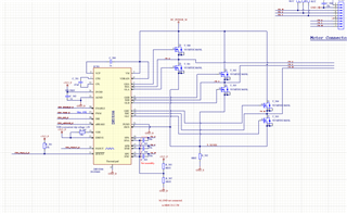
- following is my circuit.

- 8000rpm ~ 30000rpm speed control

- 15K PWM

- mcu:STM32BOG1RCT6

The problem is temperature is up to  nearly 120 Degree Celsius without load.

I checked the orders of the phase and hall has no problem.

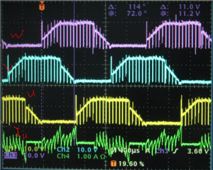
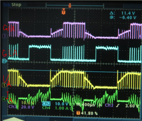
I driving the motor with another motor driver under the same condition, the temperature was only 70 Degree Celsius.

I don't know why the temperature of the motor is so high, could someone can give me some advices for this?

Thanks,

Best Regards,

Matt

  • Are there Some body has experience on a similar case?

  • Hi Matt,

    Thanks for posting your question on the E2E forum! One big factor with thermal issues is PCB layout. If the heat of the device is unable to dissipate properly through the power pad and ground plane, this will result in thermal issues. Could you provide your layout? Also, what IDRIVE setting are you using?

    Regards,

    Anthony Lodi

  • Hi Anthony,

    Sorry, I think you are misunderstanding my issues. Maybe I described not clearly. I mean the motor has a nearly 120 Degree Celsius temperature, not the driver.

    Why I have this wondering, for I driving the same motor with 2  different driving PCBAs, of which one is DRV8306, another one is a old project of our company.

    the difference between is the control method, the old one only modulate the high arm bridge MOSFET with PWM signals, the low bridge arm MOSFETs were open or close with a high or low level signal.

    I think is different from DRV8306 driver, right?

    DRV8306 drives both the high and low arms' MOSFETs with complementary PWM control signals, that means the MOSFET will not be closed completely at a phase interchange moment, so the current has a different freewheeling path. So i think there are some compensation measures  must be added, which can resolve the problem.

    Are there someone met a same problem?  

    Thanks a lot,

    matt 

  • Hi Lodi,

    Another point is that the voltage for drv8306 and the external MOSFETs is 11VDC(a 4.2V*3cells pack)~15VDC(a PD adapter for charging the battery, while as a power supply for drv8306 and external MOSFETs).

    Thanks a lot,

    Matt

  • IDRIVE connected to DVDD(3.3V) .Thanks. 

  • Hi Matt,

    Please use smaller IDRIVE settings based your MOSFETs Qgd value and the slew rate of the VDS voltage for the MOSFETs. Using max IDRIVE may be too high and can cause device heating from too high of gate drive current settings.

    https://e2e.ti.com/support/motor-drivers-group/motor-drivers/f/motor-drivers-forum/796378/faq-selecting-the-best-idrive-setting-and-why-this-is-essential

    Thanks,
    Aaron

  • Hi Matt,

    The IDRIVE setting you are using is really high for such a low Qgd MOSFET (Qgd = 2.5nC), so I expect that this is resulting in significant ringing on the MOSFETs during switching that could even result in damaging the DRV. I would recommend using the minimum IDRIVE setting of 15mA/30mA to achieve a slower MOSFET switching time that will result in better EMI performance and less MOSFET ringing. Even with the lowest IDRIVE setting that can still result in a VDS slew rate of faster than 200ns for switching the MOSFET, which is still quite fast. This could be a contributing factor to the motor heating. 

    Another thing is that it looks like from the waveforms a near 100% duty cycle is being applied. If the motor is a 12V motor then this could really be pushing the limits of the motor. 

    The DRV8306 device does operate in synchronous rectification mode which PWMs both the high side and the low side MOSFET, which results in the motor current dissipating through the low side MOSFET Rds(on) instead of through the body diode of the low side MOSFET. The motor current path is the same from a motor perspective, but the synchronous rectification will help with less power losses in the MOSFETs since the current flows through the MOSFET rds(on) instead of through the MOSFET body diode. 

    Regards,

    Anthony Lodi

  • Hi Lodi,

    Thank you very much for your information.

    Are the pointed out area in the picture below right, is it redundant? For the curves from the official data sheets has no these area.

    That were be leaded by the combination of the slower MOSFETs with very high IDRIVEs?

    Thanks,

    BR,

    Matt

  • Thank you very much for your information. It's very useful for meGrinning.

  • Hi Lodi,

    I tried to set the IDRIVE to 15mA/30mA, the temperature of the motor cooling down from 110℃ to 85℃.
    But our goal is to more or less 75℃, there are still 10℃ need to be reduced.

    I want to ask that are there some chance if I use a faster MOSFET?

    Is that means If I use a very fast MOSFET, eg. Qgd / Tr closed to 300nmA or bigger, for which i can get more choices, for i can set different IDRIVE, right?

    If i use a very slow MOSFET there are no choice, for I must have to set IDRIVE to the minimum IDRIVE setting.

    At the very beginning, I want to use CSD88584Q5DC, but for very difficult to order, i used a on hand MOSFET, that the reason the heating problem occurred.

    Is it necessary to use CSD88584Q5DC? Qgd / Tr = 26nC/24nS=1.08A, Qgd / Tf=26nC/17nS=1.53A seems crazy!!!

    Could you please give me some advice?

    Thanks,

    Best Regards,

    Matt

  • Hi Matt,

    Glad to hear that thermal performance improved with reducing the IDRIVE! The problem actually is that the MOSFET you are currently using is a very fast MOSFET, and you may consider using a slower MOSFET. A low Qgd MOSFET means that the MOSFET will switch faster, so using a higher Qgd MOSFET will mean that the MOSFET will switch slower and may need a higher IDRIVE to switch at the desired speed. 

    Targeting a rise and fall time of 24ns/17ns is extremely fast switching time and will likely cause significant ringing during MOSFET switching. With the MOSFET you have been using, with the minimum IDRIVE of 15mA/30mA the VDS slew rate is about 2.5nC/15mA = 167nS switch on time and 83.3nS switch off time, which is still very fast. Most customers consider a VDS slew rate of 200ns/100ns rise/fall time to be a fast switching speed, and depending on your design it could still be too fast for your system to handle without significant ringing. Since you can't reduce the IDRIVE any farther with the MOSFET you are currently using, you could either add a gate resistor with a value between 2 ohms and 10 ohms to slow down the IDRIVE even more, or you can use a different MOSFET with a higher Qgd to achieve a slower MOSFET switching time. If you switch the MOSFET with a speed of around 200ns or slower that may improve the motor heating issue even more since that will reduce the ringing that occurs when switching a MOSFET too fast.

    Are the pointed out area in the picture below right, is it redundant? For the curves from the official data sheets has no these area.

    The waveform that you provided is the expected behavior for GHx. The reason that the GHA waveform in the datasheet looks different than yours is because the datasheet waveform for GHA was taken with a differential probe with respect to SHA. In your waveform GHW is taken with respect to ground, and that is the waveform that I would expect to see. 

    Regards,

    Anthony 

  • Hi Mr. Anthony Lodi,

    Another question, How to fix the Imax when I assign 5A (max. current of the motor in my project), then I calculated a VDS_OCP IS 0.15V, then i connected the VDS to ADNG, the motor seems running abnormal, run 2`3 sec. and then stopped.(R_sense set to 0.33ohm  1.8V/5A=0.36OHM)

    I don't know why.

    When I set the VDS TO 0.6V(VDS Hi-Z ( > 500 kΩ to AGND)), R_sense=0.055OHM, the device running smoothly, of which the Imax seems is >30A.

    I'm so wondering about this phenomenon. Could you please give me some advice?

    Thanks,

    BR,

    Matt

  • Hi Matt,

    The VDS_OCP trip point is based off of the Rdson of the MOSFETs, not the Rsense resistor value. Since MOSFETs have a particular Rdson value while the MOSFET is on, the VDS monitors monitor the voltage drop from drain to source of the MOSFETs while a MOSFET is on, and if the voltage drop is greater than the VDS threshold then the VDS monitor will trip. You can look at the MOSFET datasheet to determine the rdson value, and calculate the VDS trip voltage based on the desired current.

    Regards,

    Anthony Lodi

  • Hi Anthony,

    Thank you very much.

    I 'm not so clear about how to determine the parameter of Imax in the Eguation bellow:

    -Rsense=VLimit/Imax
    -VLimit=1.8V fixed


    Is the Imax the maximum current of the motor, is it the peak value or RMS value, or average value?

    Because in my project the current never over 5A, but when I calculated the Rsense,

    Rsense=1.8V/5A=0.36ohm 

    With this Rsense the motor can't running normally, then I decrease the Rsense step by step(0.33*6 with parallel connection), then the motor running well.

    That means the IMax is more than 30A. 

     If not the motor will be stopped seconds later after start up.in the following Equation also need to fix the Imax:

    VDS_OCP > Imax * RDS(on)max

    The RDS(on)max=RDS(on)*1.8 also according to the datasheet of the MOSFET I used.

    If I use Imax =5A the VDS_OCP=5*7.3OHM*1.8=0.0657V, if i set VDS to the minimum value to 0.15V, the motor of the device also can not running.

    So to determine Imax and is the most key point. Could you please give me some suggestion?

    Thanks,

    Matt

  • Hi Matt,

    The DRV8306 has 2 overcurrent protection features:

    1. VDS overcurrent protection

    2. Vsense overcurrent protection. Vsense overcurrent protection is split into 2 different features:

            a. cycle-by-cycle current limiting

            b. overcurrent trip voltage.

    The cycle-by-cycle current limiting feature monitors the voltage drop across Rsense and once it reaches about 0.25V (there is a 5us deglitch time before it trips) then that will trip the cycle by cycle current limit and will turn off the high side MOSFET outputs until the next PWM cycle begins. The below figure gives a good visual of how this works.

    When you are choosing the IMAX value, the cycle by cycle trip threshold is the primary concern.

    The cycle by cycle trip threshold has a minimum of 0.225V and a maximum of 0.275V. In order to ensure that the cycle by cycle current limit feature doesn't trip too early, you may chose to base your calculations off of the min value of 0.225V.

    For your application, let's chose an ITRIP of 5A for the cycle by cycle current limit feature. In order to calculate the Rsense value, you use the equation below:

    Rsense = Vcycle_by_cycle_trip_voltage/ITRIP = 0.225V/5A = 45mohms. The worst case scenario is that the cycle by cycle current limit feature will trip at 0.275V/45mohms ~= 6.1A.

    The Vsense overcurrent protection feature is more for protection against hard shorts that may occur, where current will rise very rapidly. The Vsense overcurrent protection feature trips at a much higher current then the cycle by cycle current limit, since it trips once the voltage across the Rsense resistor reaches about 1.8V (there is a 4.5us deglitch time on the overcurrent protection feature). In your application, assuming you use an Rsense of 45mohms, the overcurrent protection feature would trip at a current of about 1.8V/45mohms = 40A. This would be more for last resort protection against a hard external short on one of the phases. 

    In order to properly set the VDS overcurrent trip voltage, You will use the equation below:

    VDS overcurrent trip voltage = Itrip x Rds(on) = 5.1A x 7.3mohms = 0.0373V. Since the lowest overcurrent trip voltage is 0.15V, then that is the closest we can get to 0.0373V. 

    Hope that clears things up!

    Regards,

    Anthony Lodi

  • Thank you very much, it's clear.Relaxed

  • Hi Matt,

    Glad to hear that! Feel free to check the "This resolved my question" button to mark the answer as resolved.

    Regards,

    Anthony Lodi

  • Hi Anthony,

    OK, I will do this.

    Could you please help to check which one is better  for my application in the below three MOSFET:

    C900305_97DA4C7253202C12CD0AB7DAC3B4367D.pdf     

    B519E92A12D7E4CA6E4BAAE877F96E7A_OK.pdf 

    C900300_DA3F3AB73895DE2BC03F768F8B189D0A.pdf

    These are the slower MOSFETs on the online market I can find.

    Could you please have to check, and then I will order for replacing the old too fast one..

    Thanks,

    Best Regards,

    Matt

  • Hi Matt,

    Using the NTMFS5C410NLT MOSFET with an IDRIVE of 105mA/210mA will result in a switch time of about 209ns rise time/105ns fall time. This seems like a good option to use.

    Regards,

    Anthony Lodi