This thread has been locked.

If you have a related question, please click the "Ask a related question" button in the top right corner. The newly created question will be automatically linked to this question.

MCF8316A: Algorithm Status Details: Motor Tuning

Part Number: MCF8316A
Other Parts Discussed in Thread: , MCT8316A

Dear Team,

Recently we received MCF8316AEVM from TI. During testing it is found that the algorithm state of the module is changing.

In the datasheet, only ALGORITHM_STATE Register Field Descriptions are provided. I would like to know more about what exactly is happening in each algorithm state.


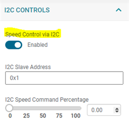
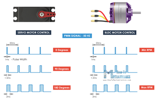
I have another query, can I configure MCF8316A without any controller with PWM input for motor rotation?

Thanks and Regards,

Sujeesh V

  • Sujeesh,

    There are 25 algorithm states in MCF8316A. Explaining what exactly is happening in each algorithm state is a cumbersome process. Let us know if you have any specific questions in these algorithm states.

    Yes, MCF8316A can be operated standalone just by applying SPEED PWM command. 

    Regards,

    Vishnu

  • Hi Vishnu,

    Thanks for the confirmation regarding standalone operation.

    Currently I'm trying to setup the MCF8316A using the evaluation board. I completed MPET to extract the motor data. The extracted values are, 

    • Motor Resistance = 0.63Ω (As per datasheet: Terminal resistance phase-to-phase=1.83 Ω)
    • Motor Inductance = 0.038mH (As per datasheet: Terminal inductance phase-to-phase=0.12 mH)
    • Motor BEMF constant = 26mV/Hz (As per datasheet: Torque constant=8.32 mNm A-1 & Number of pole pairs=1)

    After this the Algorithm state will become "Motor_Idle". After this, if I give again the Speed input using potentiometer, motor will start running for sometime and then it will stop with Algorithm state stuck at "Closed_Loop Aligned" without any fault status.

    After this, I have to reboot the evaluation board.

    Any idea what is happening?

    Thanks and regards,

    Sujeesh V

  • Sujeesh,

    Are you auto reading registers during motor operation? If so, then please do not auto-read any registers during motor operation. This is a known issue in MCF8316A.  

    Regards,

    Vishnu

  • Hi Vishnu,

    As per the tuning guide, "Auto Read Fault Status" and "Auto Read Motor Status" are enabled during the testing.

    Isn't this required during evaluation, to know the fault status, motor speed etc.?

    Also, I request you to verify the MPET outputs are acceptable or not.

    I couldn't find any option to disable the I2C communication to run the MCF8316AEVM without MSP controller. If the EVM is powered on without connecting the Micro-USB to computer, both ALRM & nFAULT LEDs will be glowing. 

    Thanks and Regards,

    Sujeesh V

  • Sujeesh,

    As per the tuning guide, "Auto Read Fault Status" and "Auto Read Motor Status" are enabled during the testing.

    Isn't this required during evaluation, to know the fault status, motor speed etc.?

    Yes, enabling auto read helps to know the status but as I mentioned, we have an errata related to enabling auto-read. Instead of enabling auto-read, you can click "Read all registers" to update the motor and fault status.

    Also, I request you to verify the MPET outputs are acceptable or not.

    Please go ahead with the MPET measured motor parameters. 

    I couldn't find any option to disable the I2C communication to run the MCF8316AEVM without MSP controller. If the EVM is powered on without connecting the Micro-USB to computer, both ALRM & nFAULT LEDs will be glowing. 

    You see the ALARM and nFAULT LED turned ON partially because both pins are not hard pulled to GND. You can just ignore this as this is not going to cause any issues. To disable speed control over I2C and control the speed using external PWM, you should disable "Speed Control via I2C", configure SPEED_MODE to "Controlled by duty cycle of speed input", choose the appropriate SPEED_RANGE SEL based on your SPEED PWM input and move the jumper J1 on the EVM to EXT. You can now apply speed PWM to EXT_SPEED test point on the EVM.

    Regards,

    Vishnu

  • Hi Vishnu,

    Thanks for the update. We configured the EVM for PWM accordingly.

    • SPEED_MODE = Controlled by duty cycle of speed input
    • SPEED_RANGE_SEL = 10Hz to 325Hz

    I had an observation. During no load testing of EVM for around 3 to 5 minutes, motor stopped running. The fault registered was Over Temperature. In the GUI I didn't see any information regarding the current temperature of the IC.

    • Is there a way to find it out?
    • Is there any predefined methods to dissipate the heat generated during loaded condition?
    • What is the maximum current the EVM is designed for?

    (Edited)

    Our PWM signals details are as follows (same as normal BLDC motor ESC),

    • Signal period = 20ms
    • Minimum pulse width (No RPM) = 1ms
    • Maximum pulse width (Full RPM) = 2ms
    • Minimum duty cycle = 0.05
    • Maximum duty cycle = 0.01

    I'm so confused with the All Tuning Settings page. I wanted linear speed from minimum to maximum. Below are my doubts,

    • What is the unit of SPEED mentioned in the All Tuning Settings? 0 to 100 is in percentage?
    • What is the unit of Duty Cycle mentioned in the All Tuning Settings? 0 to 100 is in percentage?
    • Where to provide detail about signal period?
    • How to find current Duty cycle details?

    Thanks and Regards,

    Sujeesh V

  • Hi Sujeesh,

    We do not have any registers to display the IC temperature. Overtemperature can get triggered when the motor draws high current for a longer time duration. Can you share the device configuration file (.JSON)? Go to File -->Save registers to download the file. 

    100% duty cycle corresponds to maximum speed configured in MAX_SPEED register. When 100% duty is applied, motor will spin at the speed configured in MAX_SPEED registers. At 50 % duty cycle, motor will spin at 50% of MAX_SPEED.

    Unit of duty cycle is %.

    Device  does not need the actual speed period information. You jsut need to input the range of the frequency in SPEED_RANGE_SEL register.

    You can read the speed reference (duty cycle * max speed) in  SPEED_REF_CLOSED_LOOP register. 

    Regards,

    Vishnu

  • Hi Vishnu,

    Please find the attached configuration file after configuring the PWM. Speed profiles are not set in this file.

    Sorry, I was not able to upload .json file, so I converted to PDF.

    Thanks & Regards,

    Sujeesh V

    PWM.pdf

  • Hi Sujeesh,

    Today is a holiday in the US, we will get back to you tomorrow. 

    Thanks,
    Aaron

  • Sujeesh,

    EVM is designed for 8A peak current. Do you have a current probe to measure the current drawn by the motor when speed command is issued? I checked your settings and don't see a reason why over temp should get triggered. Can you disable OTW_REP and try again? Also, did you run MPET to obtain the motor parameters R, L and Ke? 

    Regards,

    Vishnu 

  • Hi Vishnu,

    I use a tabletop power supply to power the EVM. At 24V voltage it usually draws 0.08A when the motor rotates without any load. The overheat was observed only once during my testing. And as per the datasheet of motor maximum current is around 1.6A and stall current is 9A.

    As I mentioned in the previous posts, I ran the MPET and captured the values and copied the numbers to the closed loop parameter and then disabled the MPET. Since my final application will be just running the motor with PWM input command without using as additional controller, we thought the MPET is not required every power on. I used the closest value obtained by the MPET, because during some MPET run, the value seems to be different and MPET used to stop at estimating Ke algorithm.

    Have you checked my duty cycle conditions?

    Our PWM signals details are as follows (same as normal BLDC motor ESC),

    • Signal period = 20ms
    • Minimum pulse width (No RPM) = 1ms
    • Maximum pulse width (Full RPM) = 2ms
    • Minimum duty cycle = 0.05
    • Maximum duty cycle = 0.01

    It'll be better if you can guide us to configure the speed loop according to above mentioned duty cycle, as I'm struggling to get it running as desired. We want the motor to run at maximum speed with duty cycle of 0.01. The PWM generated to control the motor are from an RC receiver usually used in UAV.

    Thanks and regards,

    Sujeesh V

  • Sujeesh,

    I see that "Speed Control via I2C" is enabled. When this is enabled, device will take the speed command via I2C. Can you disable this bit?

    So you are applying 50 Hz Speed PWM signal with min duty cycle of 5% (1/20 *100) and max duty cycle of 10% (2/20 * 100). I see that MAX_SPEED is set to 267 Hz. SPEED_MODE and SPEED_RANGE_SEL are configured correctly. When you apply maximum duty cycle of 10%, motor should spin at ~27 Hz (electrical speed). 

    Do you see the motor spin at this speed when you apply 10% duty cycle?

    I'm not sure how 0.01 will be your duty cycle at maximum speed. Can you explain?

    Regards,

    Vishnu

  • Hi Vishnu,

    I'll disable the "speed control via I2C" and check the response.

    When I'm giving 5% duty cycle the motor is running with a rpm around 3000. "Reference for speed loop" was displaying 14.7 Hz. I didn't checked at higher duty cycle.

    Regarding the duty cycle, this is the standard duty cycle used in RC vehicles. All the Electronics Speed Controller (ESC) which control brushless DC motor are programmed to accept this type of PWM signals. Even servos used in the RC plane are deflected with same PWM commands. Please find the attached image for your reference. (Arduino Brushless Motor Control Tutorial | ESC | BLDC - How To Mechatronics)

    Thanks,

    Sujeesh

  • Sujeesh,

    At 14.7 Hz reference speed, input speed command duty cycle is ~5.5% (14.7/267). Can you select "Speed feedback" from Algorithm Variable select and monitor the actual speed? Please do not enable "Auto read".  Just click "Read all registers" after the motor speed stabilizes and check the Speed feedback. Do you know the number of pole pairs in this motor?    

    We are not sure how the ESU processes the input PWM signals coming from Arduino to control the motor. If you are looking to replace ESU+Arduino with MCT8316A, I would recommend you to firstly check at what speeds (min and max) the ESU spins the motor and later try to replicate the same motor performance using MCT8316A. For now, lets ignore the PWM signals generated by Arduino.

    Regards,

    Vishnu

  • Hi Vishnu,

    Sorry for the delay in response.

    Today I checked the setup with proper duty cycle command and tested up to 60% of duty cycle. Motor was rotating properly. I used an Arduino board code to give PWM signal according to the input from serial monitor (from Laptop).

    One observation from the testing was, without connecting the USB cable from the development board to laptop the motor was not rotating. Without connecting to GUI (with USB connected to laptop) the motor was rotating as commanded.

    The new board for our application is designed without microcontroller for I2C command. Now, I have a doubt will it work or not. The schematics is given below,

    Can you just check and let me know?

    Thanks,

    Sujeesh 

  • Sujeesh,

    You can spin the motor without the GUI by writing the configurations to the EEPROM memory and commanding the PWM signal to SPEED pin. Make sure the SPEED_MODE is configured to "Controlled by duty cycle of PWM pin" and the SPEED_RANGE_SEL is configured to the frequency of the PWM signal. 

    Regards,

    Vishnu. 

  • Hi Vishnu,

    As you requested before, all the configurations are stored in the EEPROM memory and the command is given externally.

    Will you be able confirm my schematics?

    Thanks,

    Sujeesh

  • Sujeesh,

    Here's my feedback.

    1. Rbk and Cbk should be populated across SW_BK and GND.

    2. BRK can be pulled to GND via 10k resistor if unused.

    3. DIR can be connected to AVDD via 10k resistor if unused.

    3. DRVOFF pin should be pulled to GND.

    Regards,

    Vishnu

  • Hi Vishnu,

    Thanks for the feedback.

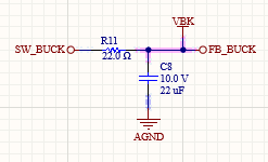
    1.  22 Ohm Rbk and 22uF Cbk are used
    2. BRK is connected to AGND via 10k resistor (mentioned in the previous schematics)
    3. DIR  is connected to AGND via 10k resistor (mentioned in the previous schematics)
    4. DRVOFF is connected to AGND via 10k resistor (mentioned in the previous schematics)

    Regards,

    Sujeesh