This thread has been locked.

If you have a related question, please click the "Ask a related question" button in the top right corner. The newly created question will be automatically linked to this question.

DRV8303: BLDC Winding current waveform is not as expected

Part Number: DRV8303

Hi,

We have been designing a BLDC driver circuit with DRV8303CAR, however when we measure current waveform via the scope, the resulting waveform is not as expected. Moreover, motor does not run at all or stop unexpectedly with PWM modulation <100%.

I attached the graph from the scope with 100% PWM duty cycle. I think that current waveform indicates a problem since current goes even below NC case. 

Yellow line is trapezoidal voltage from winding 2

Blue line is current from winding 2

* I drew red line in the scope image for the expected current waveform, however current seems to goes below

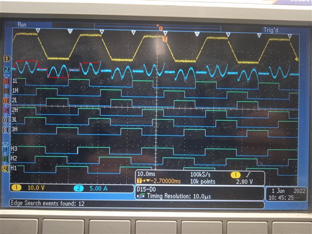
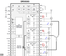
#L, #H is the INL_X and INH_X respectively - 6 PWM mode [no pwm signal for test purposes (100% duty cycle)]

H# is the hall sensor number

Counter clockwise rotation communication table

Other driver configuration.

Overcurrent Adjustment is for ~37Amp (Rdson 1.8mOhm)

Current Limit Mode

Maxon 24V BLDC motor with hall sensor

I check the registers to be sure to configurations are correct,  also fault and otwc pin for faults and warnings.

Is it normal or what could it be the reason for that waveform ?

  • additionally 

    i forgot to write some issues

    i have been polling fault and otcw pins states, which i plan to change state change interrupt.

    OC_TOFF is setted to "off-time control" not "cycle by cycle", when we set to cycle by cycle control, motor does not start thus i suspect problem occurs when GHX or GLX pins goes high.

  • Hi Ali,

    Few issues here:

    1) I would not recommending starting right at 100% duty cycle, this requires a large amount of startup current and can cause the motor to not start if there are gate drive issues with the DRV8303. Try starting at 10-20% duty cycle so there is not a large instantaneous change in current or average motor voltage switching across the FETs. 

    2) DRV8303 is a bootstrap gate driver. Even though it can support 100% duty cycle, there may not be enough bootstrap current to support 100% duty cycle immediately at startup. Trying switching the low side MOSFETs before spinning the motor to charge the bootstrap capacitors. 

    3) The Hall signals look correct. Can you check if the gate-to-source voltages for each phase appear correct? For instance, compare GH_A with GL_A and ensure that both aren't on at the same time causing a shoot through event. You'll need to zoom in close to around 100ns/div to see the gate drive behavior. SH_A should switch to your motor voltage when the high-side gate is on. 

    4) Can you share your schematic?

    Thanks,
    Aaron

  • Thank you Aaron, low side switching and not starting with 100% duty cycle helped to get usual current wave form.

    I will also check GH_A & GH_L for shoot through event and if exist correct them with DTC.

  • Hi Ali,

    Glad to hear this helped! I will close this thread. 

    Thanks,
    Aaron