This thread has been locked.

If you have a related question, please click the "Ask a related question" button in the top right corner. The newly created question will be automatically linked to this question.

Low-frequency "ripple" (note the quotes) on DC bus of AC motor drive.

Other Parts Discussed in Thread: MCF8316A

Please note that the post is generally about AC motor drives (i.e. inverters) and not particularly on TI products.

Running speed control and FOC on a low-voltage inverter, we see that the DC bus has a 0.1 Hz "charge/discharge" characterstics on top of the DC value.

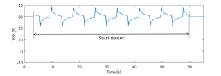
The motor drive regulates around zero speed during the segment "Start motor".
Otherwise, the PWM is inactive - i.e. the motor is in "IDLE" state.

For those who have a lot of experience working with AC motor drives, is such slow "ripple" on the DC bus normal ?

What causes it ?
Is it due to bad design of the inverter ?

Note that the bus behaves similarly if power is supplied by batteries, so this is not a feature of the DC power supply.

  • Hi Ronny,

    This seems like a question for the BLDC forum. My knowledge on AC motors and FOC is very limited. The BLDC team may be able to better answer your questions.

    Regards,

    Pablo Armet

  • Thanks Pablo, I didn't know there was a BLDC forum.

    The tool-tab "Forums" don't have a link to any BLDC. How do I find it ?

  • Hi Ronny, 

    I am from the BLDC forum. Generally linking a part number in your query from the BLDC product line (i.e. MCF8316A) leads to questions answered by the BLDC team. 

    Anyways, ripple on the supply line for an inverter power stage is likely due to small bulk and bypass capacitance. Bulk and bypass capacitance stores DC bus voltage and when the motor requires excessive current demands (such as starting, stopping, accelerating, decelerating), the current can be supplied from the capacitors so that the DC voltage does not dip or have ripples. Having a range of capacitors above 10uF rated for the supply voltage is helpful for reducing DC bus ripple. 

    Things such as supply inductance can also factor into the supply ripple. 

    Here is a training video: www.youtube.com/watch

    Thanks,
    Aaron

  • Hi Aaron.
    Just to be clear, we are talking about the capacitor C in the figure ?

    As I understand, this capacitor (or collection of capacitors) is designed to be a fast-acting power source (or sink) when large currents are required during acceleration (or large currents are generated due to braking). I.e. to help keep the DC bus at a constant level.
    Note however, that the "ripple" that I'm referring to shows up immediately when starting the PWM - while the speed setpoint is still zero.
    Also, when stopping the PWM, the "ripple" disappears.

    There is clearly a charge/discharge happening so the capacitor must be involved, but the dynamics is so slow and the waveform is so consistent that I suspect that this is happening by design and regulated by software. Do you know if this is the case ?

  • Hi Ronny, 

    Yes, that is the supply bulk capacitance. 

    0.1 Hz is very slow frequency that usually does not come from a motor system usually. PWM frequencies are usually in the 20kHz range, and device-related BLDC motor drivers use charge pumps that operate in the 450kHz range.  Anything slower than 2kHz is usually from something outside the motor driver system. 

    You may want to isolate other parts of your system (i.e regulators, motor driver, MCUs, etc.) to systematically debug the source of the noise. I would be surprised if this comes from the motor driver. 

    Thanks,
    Aaron

  • UPDATE:

    0.1 Hz = 10 times/second = 600 RPM. This is likely due to motor commutation causing this ripple to occur at C, the bulk capacitance in the power stage. Likely large current ripple is causing this charge/discharge behavior from the C bulk capacitor. Ways to fix this includes:

    - Lowering the PWM frequency (i.e. 20kHz to 10kHz)
    - Increasing the bulk capacitance C (i.e. from 330uF to 330uF * 3)

    Thanks,
    Aaron