This thread has been locked.

If you have a related question, please click the "Ask a related question" button in the top right corner. The newly created question will be automatically linked to this question.

MCF8316A: Exactly what parameters does MPET tune? Is there any way to read them out once written to EEPROM?

Part Number: MCF8316A

Hello,

I'm working on a design using the MCF8316A to spin a custom BLDC motor with a magnetically levitated bearing. Actually, we are still using the pre-production PMCF8316A parts if that makes a difference.

I'm in a strange situation: I have one chip where I successfully ran MPET and burned everything to the EEPROM. That one works great. I want to program another part to perform the same, but now I can't run MPET because something about the first step is causing our magnetic suspension to fail. The suspension isn't TI's problem of course, but it seems like I should be able to replicate the performance of the working part on a second one without running MPET. We need something working in the short term for an important test. I'd also like to increase the ramp rates on the part that is working well, but I don't think I can without overwriting the magic parameters.

I know how to bypass MPET by manually writing MOTOR_L, MOTOR_BEMF_CONST, and MOTOR_R to the values that I think are right (3.4 ohm, 0.125mH, 2 Ke), then writing SPD_LOOP_KP to 10 and SPD_LOOP_KI to 1 as default values suggested on a previous post on this forum. Running with those parameters does spin the motor, but it draws at least 100mA more than the MPET-tuned parameters saved to the EEPROM. This is with the same chip. My question is: what else is MPET tuning? CURR_LOOP_KP and CURR_LOOP_KI? I tried manually adjusting the current and speed loop KP and KIs in real time, but none of them seem to have an effect on current draw once it's in closed loop aligned state.

One strategy is to try and read out what is saved in the EEPROM so I can write the same values to another part. When I run the GUI (version 1.0.1 since we are using PMCF parts) with the working chip and click "Read from EEPROM", I get a message saying the command was successful, but the MOTOR_L, MOTOR_BEMF_CONST, and MOTOR_R registers still read 0 and the corresponding "Algorithm Variable Status Select" boxes still read "Self Measurement". Am I doing something wrong?

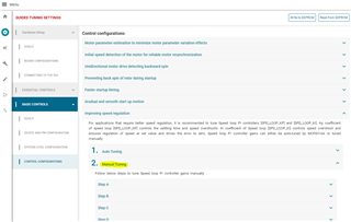
A related question: section 7.3.13 of the datasheet says "The estimated speed loop KP and KI setting can be used as an initial setting only and TI recommends to tune these parameters on application by the user based on the performance requirement.". How exactly do I do this? As far as I can tell, once it's in closed loop aligned state I can change the speed loop KP and KI to any value I want and see no change. Am I missing something?

Thanks,

Mitcham

  • Mitcham,

    I'll get back to you shortly. 

    Regards,

    Vishnu

  • Hi Mitcham,

    Thanks for your patience! Yes, the second unit should work without running MPET if the same configuration works well on the first unit. Is the device drawing 100 mA more after writing the MPET measured parameters? MPET measures electrical and mechanical parameters in PMCF8316A. Based on these parameters, it calculates current and speed loop Kp and Ki. After, reading all registers, can you check the Motor parameters in the "All tuning" settings page as shown below?

    To manually tune Speed loop, can you follow "manual tuning" steps as shown in Guided tuning section?

    Regards,

    Vishnu

  • Vishnu,

    Unfortunately I don't have access to the system right now since it is being used for other testing. What I previously observed is that when I manually wrote the R, L and Ke values and set speed loop KP and KI to 10 and 1 respectively, it would spin but draw 100mA more current than what is in the EEPROM. If I start from a fresh power cycle on the part that has values saved in EEPROM and click read all registers, I think I still see zeros for those motor parameters. I'll have to confirm when I can access the system. You are saying that I should see the saved values there? And if I enter those saved values in the second part it will work the same way? What about the speed loop KP and KI?

    I had not seen that manual tuning section for KP and KI. I'll try that procedure when I get a chance.

    Thanks,

    Mitcham

  • Mitcham,

    Yes, the second device should behave exactly the same way as the first device if both devices are configured the same. Heres' what I would recommend you to do.

    1. Power up the first device and click "Read all registers". This updates the shadow registers of all the EEPROM registers. 

    2. Go to File ->Save registers. This creates a JSON file with all the configurations in the second device.

    3. Now power up the second device. GO to File ->Load registers and upload the saved JSON file.

    4. Spin the motor using the second device. You should be seeing same performance as the first device.

    Regards,

    Vishnu 

  • Hi Mitcham,

    Do you need assistance on this still? If not, please mark as "Resolved".

    Thanks,
    Aaron