This thread has been locked.

If you have a related question, please click the "Ask a related question" button in the top right corner. The newly created question will be automatically linked to this question.

DRV8306: DVDD [PIN 26] of DRV8306HRSMT is showing 4.2 to 4.8V

Other Parts Discussed in Thread: DRV8306

We have used DRV8306 for driving a censored BLDC.

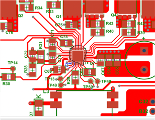
Attached is schematic of our motor driver card.

We have taken reference of DRV8306 EVM to sketch our schematic. ( Attached herewith)

We have observed that the pin 26 which is a power domain pin whose max o/p is 3.8V as per datasheet.

On our board we can see DVDD is of 4.2V

We tried isolating the DVDD net on the board. Even if the net is alone itself ( when not connected to any other section on board ) its still showing 4.2V
Please provide expert advise this matter.

DRIVER_CARD_V1.0.pdf1157.MD009E1(001)_Sch.PDF

  • Hi Shivam,

    Can you check the ground connection of your board? I see DVDD bypass capacitor C69 is referenced to GND and the DRV8306 ground is referenced to GND_FIELD_SIGNAL. Make sure these grounds are connected well and that there is not any voltage difference between the two grounds. 

    What is the voltage rating of the DVDD capacitor, and is this capacitor placed close to the DRV8306 DVDD pin?

    Thanks,
    Aaron

  • Hi Aaron,

    We have used common mode choke to +24V. And after the common mode choke we are referring +24V line as VM ( Motor Voltage )

    This is done to achieve isolation of conducted EMI as same +24V in used on the board for analog instrumentation circuits.

    In the same manner we have used dedicated ground plane for control circuit & power circuit.  And we shorted both grounds via Zero ohm, ( or ferrite bead in future based upon tests )

    I am attaching snapshots of circuit & layout to give you better understanding.

    We have checked that there is no difference of potential in 2 ground levels.

    Regarding capacitor C69, connected to DVDD we have used 885012207103 from Wurth

    Its a 50V capacitor.

  • Hi Shivam,

    Can you show waveform of VM and DVDD at powerup? 

    The component is probably just covering it in the layout, but can you confirm there are vias connecting the PGND pin and thermal pad to the GND_FIELD_SIGNAL layer? (black circle)

    Also can you confirm the GND signal connected to AGND pin (blue circle) gets connected to the GND layer? Just want to ensure the ground return paths are appropriate and do not have a large amount of parasitics. 

    Other suggestions:

    - I see IDRIVE and VDS are connected to 3.3V directly. This shouldn't use much current. Is +3.3V connected to any other circuits that may have drawn more than 30mA and caused damage to DVDD?

    - Is DVDD bypass cap C69 soldered correctly? 

    - Does this happen on only one board or multiple boards? To determine if the issue is board level or device level, could you perform an ABA swap?

    - Is ENABLE on or off when DVDD is 4.2V?

    - Can you check impedance of DVDD pin to AGND and compare to a known good DRV8306 device to see if there is any pin damage?

    Thanks,
    Aaron

  • Hi Shivam,

    Do you need assistance on this still? If not, please mark as Resolved.

    Thanks,
    Aaron