This thread has been locked.

If you have a related question, please click the "Ask a related question" button in the top right corner. The newly created question will be automatically linked to this question.

DRV8350: High DC Current flow

Part Number: DRV8350

Hello,

we have a problem with current flow to motor under special conditions.

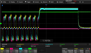
We use the 1 PWM mode.

We have 2 Problems.

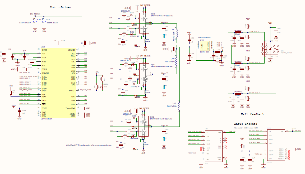
At Startup a high current flow, so that the voltage drops .

Green 24V form the powersupply.

The other signal are the current flow trough the coils.

This happens sometime after enable the motordriver.

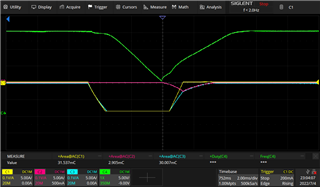
The scond problem is, that if we stop the motor physicaly,

a high dc current is flow through the motor

I think that is because of the simple statemachine inside of the controller.

If there is no more hallsensor signal, it stays in the statmachine within the block commutation.

Is this right?

thanks Andreas

  • Hi Andreas,

    Thanks for reaching out!

    Let's first discuss potential causes of problem 1:

    1. What capacitors have you placed on the 24V rail? Are they close to the DRV8350?
    2. What MOSFETs are you using?
    3. What is your IDRIVE current?

    Potential causes of problem 2:

    1. Is the motor at a complete stop (0 rpm)
    2. What is the frequency and duty cycle of your input waveform?

    Thanks!

    Tyler McCulloch

  • Hell Tyler,

        1. What capacitors have you placed on the 24V rail

        2 * low ESR alu capacitor and 2.2uF ceramic

         Are they close to the DRV8350?

       Yes

      2. What MOSFETs are you using ?

    IAUC60N04S6N031HATMA1

      3. What is your IDRIVE current?

      600mA, but he have testet all other currents ...

    Potential causes of problem 2:

         Is the motor at a complete stop (0 rpm)

         Yes

          What is the frequency and duty cycle of your input waveform?

          5 Khz    and 10% - 60%  duty cycle

  • Hi Andreas,

    For Problem 1:

    Your IDRIVE setting is quite high. Based on the Qgd of the FET you've selected, your rise time at the gate of the FET (trise) is 8 ns. We don't recommend trise to be faster than 100 ns. The current setup may cause coupling of the high side FET source into the gate of the low side FET, turning the low side FET on temporarily and causing a shoot-through event. This will cause excessive current draw from the power supply which could lead to the dip seen in the power rail. Monitoring the FET gate voltages on one phase of the motor with an oscilloscope is a good way to see if shoot-through is occurring. 

    We recommend lowering your IDRIVE to 50 mA. This will keep a fast trise time of about 100 ns and prevent shoot-through events.

    Could you provide the value of the low ESR capacitors on the 24V line?

    For Problem 2:

    If the motor is held in position physically (0 rpm) the internal state machine will react in the way seen in the oscilloscope trace. Current will increase to compensate for the increased torque on the motor. The output phase traces are what we would expect to see given the information provided.

    Thanks!

    Tyler McCulloch

  • Hi Tyler,

    maybe it is easier if i send the part of the schematic ...

  • Hi Andreas, 

    Thanks for the additional info - will review further and follow up soon

    Best Regards, 
    Andrew 

  • Hi Andreas,

    I've got a couple questions about your design that might help us determine the cause of Problem 1.

    1. What are the inductors for on your Motor U, V, and W lines?
    2. Why is there additional capacitance on those motor lines?
    3. Have you measured the voltages at the gates of your FETs on startup? This is a great way to check for a shoot-through event? I would recommend taking these measurements with the current IDRIVE setting and then the lowest IDRIVE setting.

    I will continue looking into this with the team. Thanks for your patience!

    Tyler McCulloch

  • Hi Tyler,

    the additional components are only to reduce radiation -> EMC

    I will measure the gate voltage again.

    But we found out a strange behavior ....

    It only happens if the rotor is in a certain position -> it depends on the status of the hall sensors

    Thank you for your support

    Andreas

  • Hi Andreas,

    I will continue to consult with the team to help fix the 24V rail drop issue.

    Let me know how your testing goes!

    Tyler McCulloch

  • Hi Tyler,

    we found out, that the problem only occurs, when only one halls sensor ist active.

    If we spin the motor manualy to a position with to active sensors, then there is no voltage drop when we enable the driver.

    The work arround that works for us, is to enable the driver, and then power the 5V rail of the sensor.

    So it seems not to be a shoot-through event

    Andreas

  • Hi Andreas,

    Could you clarify what you mean by "hall sensor is active"? Does this mean the sensor is powered or that the sensor is providing logic high feedback to the microcontroller? 

    Following the previous question, why are the sensors not powered on before or at the same time as the driver? The driver needs the hall sensor feedback to commutate the motor.

    Thanks!

    Tyler McCulloch

  • Hi Andreas,

    Do you still need assistance on this thread? If not, please mark as Resolved. 

    Thanks,
    Aaron