This thread has been locked.

If you have a related question, please click the "Ask a related question" button in the top right corner. The newly created question will be automatically linked to this question.

parameter questions

Other Parts Discussed in Thread: TIDA-010056

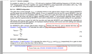
In the datasheet(<<DRV835x 100-V Three-Phase Smart Gate Driver>>) page 68,what is the definition of tr, and what is the difference between it and tr in the mosfet parameters, and how to calculate the current when charging the gate? Is it Vvcp/Rg or DRIVEP,because in the example Vvcp/Rg>IDRIVEP.
  • Hey 国武 李,


    I can try to provide some definitions which would be helpful.


    The tr refers to the MOSFET’s rise time and relates to the slew rate of the MOSFET. It determines how fast a MOSFET turns on.


    Tr = QGD/ISource


    Or for this case you can set the IDRIVEP to be greater than the QGD/tr. Where QGD is a MOSFET parameter and tr is your desired rise time to turn on the MOSFET.


    The current when charging a gate or the IAVG = QG * #MOSFETs switching * Switching Frequency


    I hope this offers some clarification. Please feel free to ask any more questions you might have.


    Also, this app note on Understanding Smart Gate Drive, might prove useful for some key definitions and formulas.


    https://www.ti.com/lit/an/slva714d/slva714d.pdf


    Best Regards,
    Akshay

  • Dear Akshay,

    Thanks for your prompt reply.I'm a mechanical student and a beginner in motor drive.So some questions may be more basic, I hope you can understand.

    First of all, I haven't found a detailed explanation of TI's official mosfet parameters. And the mosfet time parameters I searched elsewhere have different definitions. For example tr, a definition is that tr represents the time interval between VDS falling from 90% to 10% of rated voltage. ID starts to rise and is considered to be the major turn-on losses during this period.but the other is that tr represents the time interval between ID rising from 10% to 90% .

    Second, the gate drive current is not well understood. In the evaluation board TIDA-010056(TIDA-010056 参考设计 | 德州仪器 TI.com.cn), there is no external separate resistance for the gate.The charging current IG is equal to :dividing the gate output voltage Vvcp (10V) by Rg (mosfet internal gate resistance 1.4 ohms) is greater than IDRIVE (1A peak source current).(www.ti.com/.../slyy169.pdf So in the actual circuit does it turn on the gate by charging the parasitic capacitance with IDRIVE(1A peak source current)?If not, which formula is used for the average charging current during the charging process when the gate is turned on? How does it relate to IDRIVE?

    Best Regards,

  • Hey 国武 李,


    I will consult with the team and aim to provide a response before the end of the week.


    Best Regards,

    Akshay

  • Hello 国武 李,


    You are correct the MOSFET rise time (tr) represents the time taken for VDS to fall from 90% to 10% of the rated voltage. This is how it appears if we look at the system’s drain to source voltage difference. In order to turn on the MOSFET you have to apply current to charge the gate of the MOSFET.


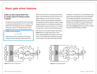
    The gate drive current is the current being used to turn on the MOSFET. For our devices with Smart Gate Drive, we have a customizable Gate drive current called IDRIVE. This value determines how fast the MOSFET turns on.


    The current isn’t applied at maximum amplitude for the whole duration. It is applied as a PWM and the average current applied on the MOSFETS can be calculated using the equation for IAVG in the Understanding Smart Gate drive app note.


    Please consult the following video for understanding some MOSFET parameters and the app note for understanding our smart gate drive system.


    I hope this offers some clarification. Please feel free to reach out if you have any more questions.


    Best Regards,

    Akshay