This thread has been locked.

If you have a related question, please click the "Ask a related question" button in the top right corner. The newly created question will be automatically linked to this question.

DRV8244-Q1: The value of the resistance that can be connected to the enable pin ( range)

Part Number: DRV8244-Q1

Hello Team

I designed a circuit that uses only the SPI communication of the DRV8244-Q1.

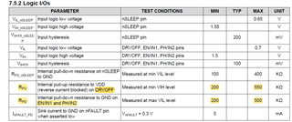
Since each enable pin for hardware control is unnecessary, the circuit is connected to GND.(EN_IN1,PH_IN2,IPORI,DRVOFF)

When connecting this pin to GND, please tell me if there is a recommended range of resistance when using a resistor to make a GND connection.

Since the DRVOFF pin has a built-in pull-up resistor, it is expected that it will malfunction due to an external resistor.
I especially want to know the recommended resistance range for this pin.

Can you tell me the internal resistance value of each enable terminal?

Thank you regards.

Onogi

  • Hey Onogi, 

    In 9.2 Typical Application in the datasheet you'll find options and recommendations for these pin connections.  It says these pins can be left floating or connected to ground:  EN_IN1, PH_IN2.  IPROPI should be tied to ground if it isn't needed.  DRVOFF should be connected to ground if it isn't needed.  You don't need a resistor connecting them to GND.  There are some more details about the recommended external components in Table 8-2. External Components Table for SPI Variant.

    I think 7.5.2 Logic I/Os will answer your question on the internal resistance pull up/down of each enable terminal - looks like for EN_IN1, PH_IN2, and DRVOFF it's between 200-550K

    Cheers, 

    Jacob Thompson

  • Hey Jacob,

    Thank you for your answer.

    I understood that no resistor connection is needed.

    My understanding is that the DRVOFF pin pull-up is 200-550KΩ and EN / EN1 and PH / IN2 are 200-500KΩ. Is this understanding correct?

    There is a reason why you want to attach a resistor to the DRVOFF pin and connect it to GND.The DRVOFF pin and VM pin are placed next to each other.

    If these terminals are short-circuited, the main power supply will go down, so I would like to protect it by connecting a resistor instead of connecting the DRVOFF terminal directly to GND.

    What happens if a 15KΩ pull-down resistor is connected to the DRVOFF pin?
    Are there any possible concerns?

    With best regards.

    Onogi

  • Hey Onogi, 

    My understanding is that the DRVOFF pin pull-up is 200-550KΩ and EN / EN1 and PH / IN2 are 200-500KΩ. Is this understanding correct?

    Yes, that is correct.  

    Ahh I see the desire for the pull down resistor.  According to 7.1 Absolute Maximum Ratings, the DRVOFF pin can handle up to 40V, so even if it did short to VM the device would be okay.  

    For adding a pull-down resistor, you need the voltage read by the DRVOFF pin to be less than VIL (input logic low voltage in 7.5.2) of 0.7V.  The DRVOFF pull up resistor is connected to VDD, the logic I/O voltage (typically 3.3V or 5V).  Using 5V for VDD and a worst-case of 200k internal pull up, I calculate 0.35V on DRVOFF which is less than VIL=0.7V.  So yea, a 15K pull down resistor should work there.  

    You might find the Functional Safety Information document interesting, it details the Failure Mode Analysis of pins on the device in failure scenarios including pin short-circuited to supply.  Of course, this relates to the damage in relation to the DRV8244 chip not your main power supply  

    Regards, 

    Jacob