This thread has been locked.

If you have a related question, please click the "Ask a related question" button in the top right corner. The newly created question will be automatically linked to this question.

DRV8424: DRV8424 design

Part Number: DRV8424

Dear experts,

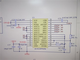
I need to control the four-channel brush motor, the input voltage is 24~ 32V, the single-channel output current needs to 2A, no additional functions, is a simple PWM control. I want to use drv8424ppwpr like this :pin22~pin25 for PWM wave, pin5/6 for motor 1, pin9/10 for motor 2. Pin17 ~21 and Pin26 ~28 hang in the air. Is this kind of circuit risky? I need to use two DRV8424, so do I need two 100uF capacitors for VM grounding? Can I share one?


Best regards,
William

  • Hello William,

    I would recommend going through the datasheet pin by pin to see if leaving the pins on a high Z state is suitable for your design. There are many situations in which you will not be able to access any features that the device already has implemented such as decay mode selection, current limiting threshold, low power sleep mode and High Z. The best way to determine if this is something that is acceptable to your system would be to go through each of the pins in your design and see if the Hi Z state is something that is acceptable for your circuitry rather than simply leaving it floating. For example, for the TOFF and circuit, we can see that the decay time would be 24us. This particular information can be found in the datasheet on section 6.5. One guidance I will recommend is that you should also read the recommendations for each pin, for example, there needs to be a capacitor between CPH and CPL for the charge pump to work effectively, the size of this too can be found in the datasheet on table 5-1. 

    Best,

    Pedro Arango Ramirez

  • Dear Pedro Arango Ramirez, 

    Thanks for your quickly reply!

    Is the circuit of the accessory feasible? Vsio1 is the output of a digital isolator with an isolated power supply and is 5V

    Best Regards,

    William

  • Hi William,

    This circuit schematic looks completely feasible to me:

    • nFAULT is properly pulled up to 5V
    • Assuming that the isolator is stable, Vref is set to 3V which will give you an Itrip of 2.3A per section 8.2.2.2 of the datasheet
    • CPH and CPL are properly tied together
    • nSLEEP is tied to logic high so it will never enter low power sleep mode
    • Decay pins tied to 5V will be low decay
    • All of the inputs are connected via PWM which is good however 

    Technically it all looks good, however I want to emphasize that in order for this to work you need to have the part number that supports PH/EN and PWM input. This would be the DRV8424E. If you try to do this with a part that only has STEP/DIR it will not work. 


    Best,

    Pedro Arango Ramirez

  • Dear Pedro Arango Ramirez, 
    Thank you for your answer!
    What did you mean by that last paragraph:
    I'm using drv8424p,Is there any problem with this?

    Best Regards,

    William

  • Hi William,

    Sorry if my answer was confusing, your DRV8424P is perfect for this application. 

    Let me elaborate, the DRV8424 has 3 different variants that will change how the device is controlled:

    DRV8424 will be controlled by STEP/DIR

    DRV8424E will be controlled by PH/EN

    DRV8424P will be controlled via PWM. 

    Because you are using PWM to control the part, the DRV8434P is the best choice. 

    Best,

    Pedro Arango Ramirez

  • Dear Pedro Arango Ramirez, 
    Thank you for your answer!
    Now every thing is well, thank you !

    Best Regards,

    William