This thread has been locked.

If you have a related question, please click the "Ask a related question" button in the top right corner. The newly created question will be automatically linked to this question.

DRV8323R: buck output supply issue

Part Number: DRV8323R

Hi team,

Here's an issue from the customer may need your help:

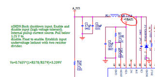
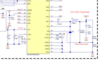
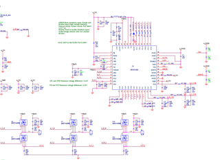
DRV8323RH is used. The MCU is powered using the on-chip internal buck output of 3.3 V and the schematic is as follows.

The 3.3-V waveform is relatively good when the power-up motor is not spinning, while at high speeds the 3.3-V waveform is subject to significant interference (up to 4 V momentary).

The customer would like to know how can the buck output supply included with the DRV8323RH chip be left undisturbed. Can this buck output supply be used by an external MCU? (3.3-V supply output in layout does not overlap adjacent layer to +VBAT1)

Could you help check this case? Thanks.

Best Regards,

Cherry

  • Hi Cherry,

    My guess is when the motor is spinning, the battery voltage +VBAT1 may be noisy and having transients or interference that is affecting the 3.3V buck output. 

    Is the +VBAT1 that supplies VIN steady? Is there large bulk capacitance on +VBAT1? Is the VIN bypass capacitor rated for 2x the battery voltage and placed close to the VIN pin of the DRV8323RS?

    Thanks,
    Aaron

  • Hi Aaron,

    Thanks for your support.

    +VBAT1 is powered directly from a 6S battery (20~26.4V) and can achieve a maximum continuous discharge current of 120A (up to 20~30A at high speed).

    There is a 680uF/35V electrolytic capacitor from the +VBAT1 input to the governor board.  The chip VIN is a 10uF 50V tolerant filter capacitor as shown in the figure.  The capacitive swing is placed slightly away from the back of the chip due to front-side space problems.

    Also, could you help recommend the capacitor inductance model for the above buck output? Is the value listed in the above figures OK for the estimated 3.3-V current within 400 mA? Or are there recommended reference values? 

    Thanks and regards,

    Cherry

  • Hi Cherry,

    Could the customer add more electrolytic capacitance to the 680uF/35V capacitor in parallel or use a larger capacitor? 35-V rated supply bulk capacitance is likely not high enough and can cause capacitance derating when exposed to a higher DC bias (i.e. 25V or higher), so the effective capacitance could be reduced. I would recommend 50-V minimum rating for this capacitance. 

    Likewise with the VIN cap, if it is placed on the back side of the board slightly away from the DRV8353RS, then it can also have capacitance derating due to trace length and if the trace is thin. Having higher VIN bypass capacitance can help keep VIN stable. 

    For the inductance model, I see that the EVM uses 330uH and the customer uses 4.7uH, so there can be a much higher current ripple due and voltage swing due to smaller inductance. Could increasing the inductor to a higher inductance assist with this ripple or interference?

    Thanks,
    Aaron