Other Parts Discussed in Thread: TMS320F28379D
To whom it may concern,
We've been dealing with a critical issue using the DRV8881P H-bridge Driver chip where the output is not linear as we expected it to be when given a PWM from a TMS320F28379D C2000 MCU. Here is some more information:
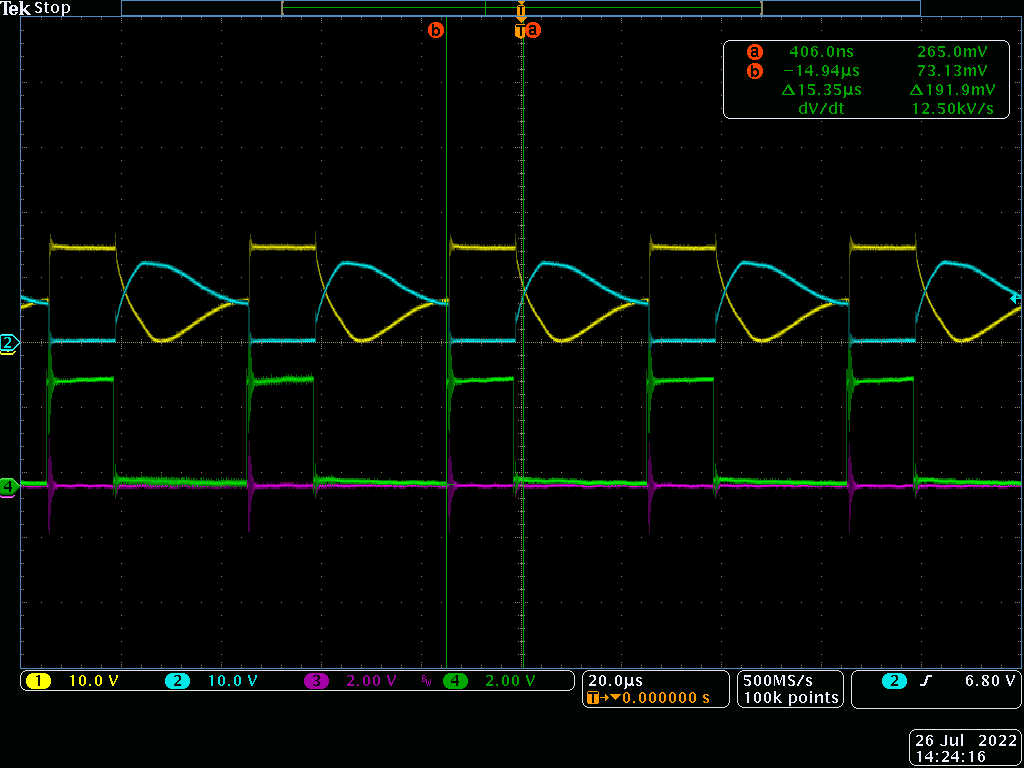
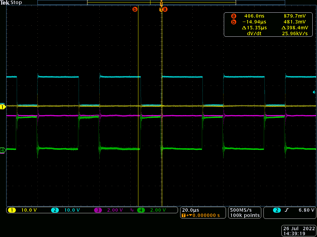
The h-bridge behaves oddly at lower PWM duty cycles. Normally the Effective voltage follows V = (Duty%) * (Rail Voltage) and should average out to be a linear relationship. Below is a .zip file which includes a PWM sweep test we conducted with oscilloscope screenshots and data we collected by probing the H-bridge outputs, two of the lines (line 1 blue and line 2 yellow) are measuring the h-bridge output voltage, one of the lines (line 3 pink) is measuring the h-bridge output current on one of the h-bridge output lines. Each test was at a different PWM duty cycle and frequency.
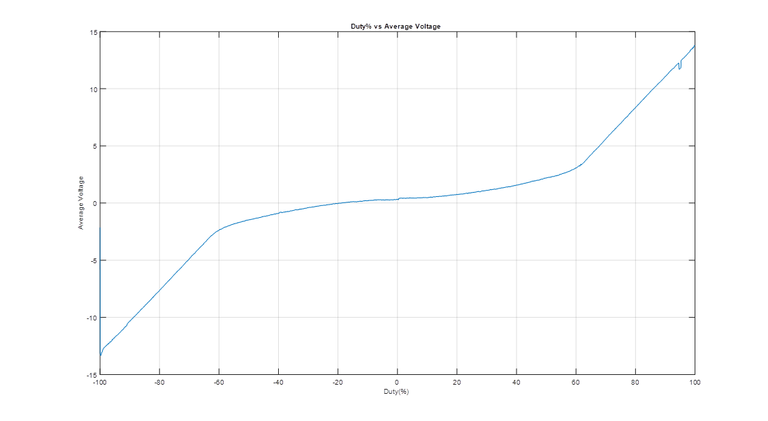
Below is what we see from a low-passed voltage output vs Duty% input. As you can see it does not follow a linear relationship at all:
Some additional information:
- Bus voltage is 15VDC
- H-Bridge current limit is set to ~1 amp
- Motor has resistance of ~14 ohms and inductance of 1.2 mH
- PWM update frequency we have tested at both 25kHz and 100kHz, PWM peripheral clock frequency is 100 MHz (MCU clock frequency / 2 = 200 MHz / 2 = 100 MHz)
- This non-linear relationship has only been seen when the motor is connected. With a resistive load, it is linear
We are using the TMS320F28379D (C2000) MCU to generate the PWM signal.
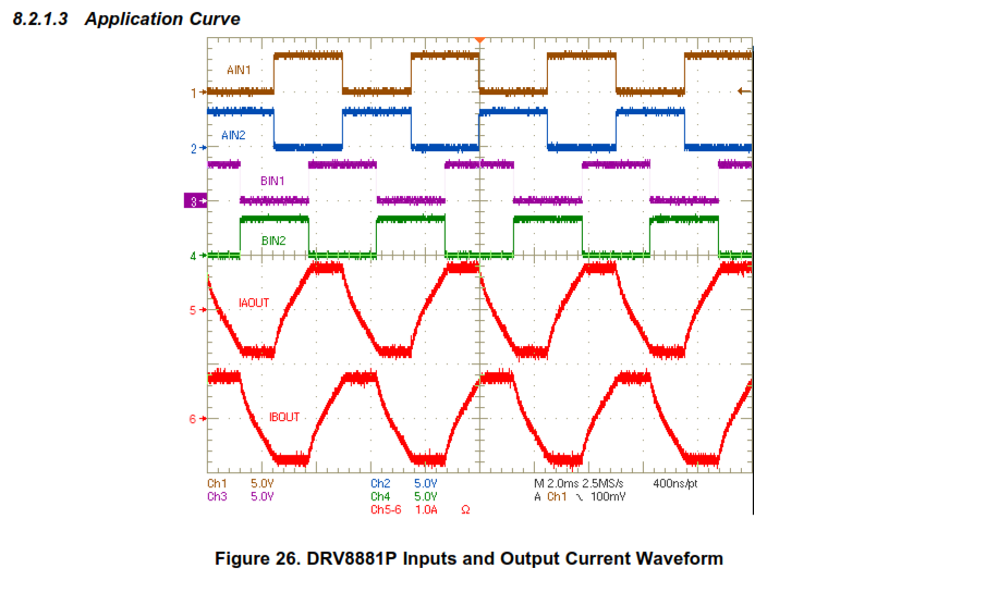
It seems the DRV8881P H-bridge datasheet specifies a particular type of PWM where both lines are driving a duty cycle (see screenshot below)? However, the C2000 is currently programmed to output a duty cycle on only one line at a time, either IN1 or IN2, which indicates the forward or reverse direction. Perhaps this is part of the issue and we are generating the PWM incorrectly (dual duty cycle vs. single duty cycle)? In which case, I could use some assistance with the C2000 software to properly generate a PWM signal compatible with the H-bridge (example code and/or callouts to the TRM would be helpful).
So essentially this issue boils down to:
Why is the H-bridge output non-linear? Are we driving the PWM signal incorrectly? Is it an electrical issue? Did we select the wrong H-bridge chip? etc.
Thanks!