Hi Experts,
Asking assistance and clarification on these queries:
In the example from the link above, they're stating that 16krpm Mech equals 62.5uS per rotation. How is this value calculated?
I initially thought it was Mrpm/60 = Mrps, 1/Mrps = Mspr and then Mspr/1E-6 = Muspr. What I'm seeing in the response is that 1/16krpm gives 62.5uS per rotation which is incorrect is 62.5 uM per rotation because there wasn't a conversion.
In this response it's also stating that the RPM can be divided by 5 to get the dead time, can you explain this to me?
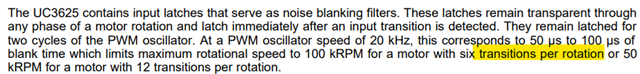
Also, as highlighted above, what really means by "transition"? As I understand it, it refers to the steps/position of rotor to complete the revolution, correct? Or, are the transitions related to the Tachometer? The Tachometer on this chip triggers whenever there's a change in state for the Hall effect sensors.
In the current system of my customer that is 6 because there are only 3 hall effect sensors, but in the Datasheet it mentions there could be 6 transitions or 12 transitions, which deters me from thinking it's related to the tachometer.
Hope to explain these queries to me.
Thank you very much.
Regards,
Archie A.
PN: UC1625